

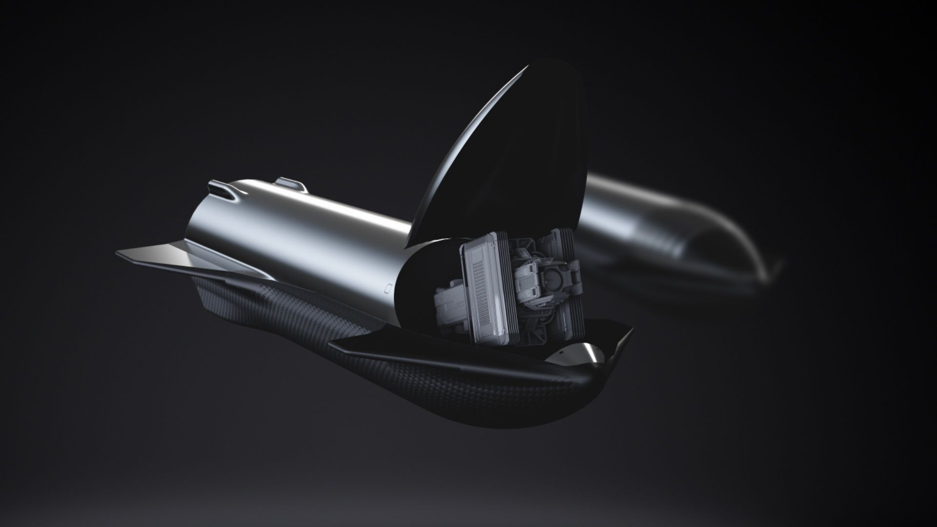
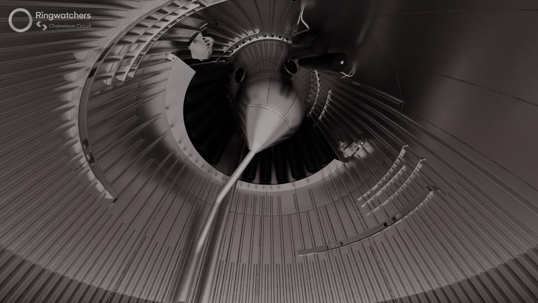
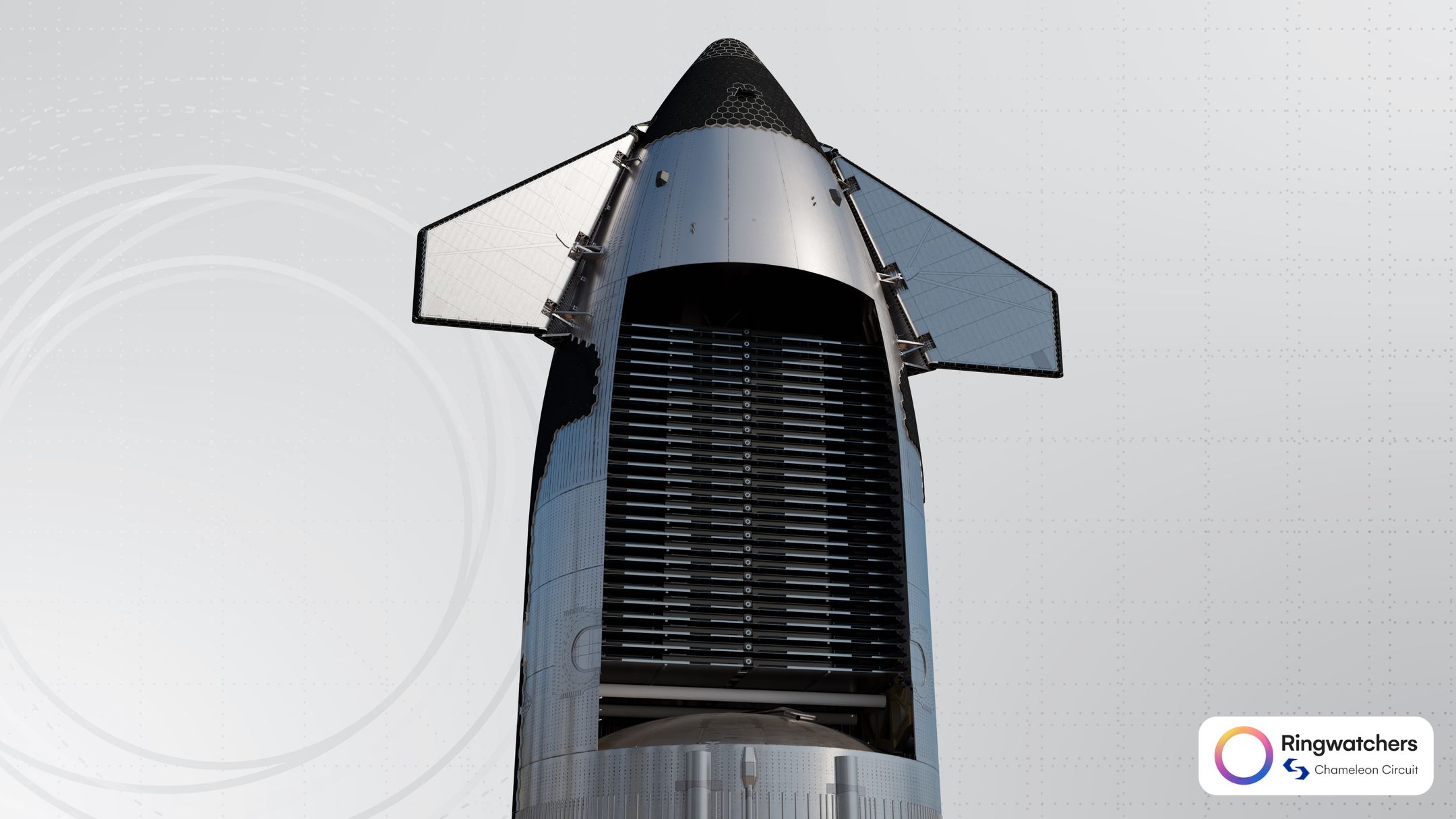
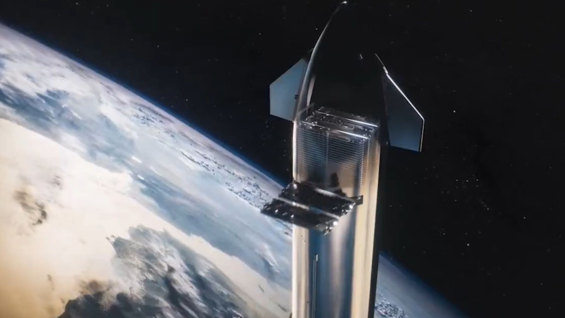
Starlink 部署序列期间的 Starship。|渲染图由 Chameleon Circuit 提供
Starship's aspirations of carrying massive payloads to orbit have existed since it was first announced as a conceptual design. While there are still countless things to do before this is achieved, SpaceX's next-generation series of ships set the stage for the future of Starship's payload capabilities.
Starship 将大量有效载荷送入轨道的愿望自首次作为概念设计宣布以来就一直存在。虽然在实现这一目标之前还有无数的事情要做,但 SpaceX 的下一代系列飞船为 Starship 未来有效载荷能力奠定了基础。
With the upgraded Ship 33 prototype, SpaceX has completely redesigned and simplified several critical systems related to how Starship carries and deploys the Starlink V3 satellites, paving the way for Starship to carry its first (actual) payloads into orbit in the near future.
通过升级后的 Ship 33 原型,SpaceX 完全重新设计和简化了与 Starship 如何携带和部署 Starlink V3 卫星相关的几个关键系统,为 Starship 在不久的将来将其第一个(实际)有效载荷送入轨道铺平了道路。
While [the stuffed banana] will remain inside the vehicle at all times, and will not be deployed today, it did give us a chance to do a test run of payload approval processes with the FAA, and that's something that we're hoping to do next year if we start flying our first Starlink satellites on Starship.
虽然 [酿香蕉] 将始终留在车内,今天不会部署,但它确实让我们有机会与 FAA 进行有效载荷审批流程的试运行,如果我们明年开始在 Starship 上飞行我们的第一颗 Starlink 卫星,这就是我们希望明年做的事情。
-- SpaceX 高级质量工程经理 Kate Tice,Flight 6 Broadcast,2024 年 11 月 19 日
There are several fascinating details about this upgraded payload compartment, and if you have not read our article about the payload deployment system for the previous generation of ships, it is highly recommended that you do so before continuing.
关于这个升级的有效载荷舱有几个有趣的细节,如果您还没有阅读我们关于上一代舰船有效载荷部署系统的文章,强烈建议您在继续之前先阅读一下。
This is the fourth of five articles covering the revised ship and will specifically discuss Ship 33's optimized payload bay, revised payload door, and completely redesigned PEZ dispenser. For the best experience, we recommend reading this article series in sequential order.
这是介绍修改后的飞船的五篇文章中的第四篇,将专门讨论 Ship 33 的优化有效载荷舱、修改后的有效载荷门和完全重新设计的 PEZ 分配器。为了获得最佳体验,我们建议按顺序阅读本系列文章。
Information Notice 信息通知
本文中的所有信息和图像均是从公开可用的来源构建和收集的,并通过对图像的推测和比较得出。请注意,以下大部分信息都是基于对图像的解释的推测。
Part X - The Payload Bay
第十部分 - Payload Bay
Since the earliest days of the Starship program, observers have long been anticipating the gigantic payload bay and door that SpaceX has claimed this vehicle will eventually feature. These initial concepts often included a giant "clamshell" style door to release large payloads. As of publishing, this design has not been implemented.
从 Starship 计划的早期开始,观察家们就一直在期待 SpaceX 声称这艘飞船最终将配备的巨大有效载荷舱和门。这些初始概念通常包括一个巨大的“翻盖式”门,用于释放大型有效载荷。截至发布,此设计尚未实现。
In early 2022, SpaceX began producing initial prototypes for a Starlink-optimized solution, known as the "PEZ dispenser", named after the rectangular candies and accompanying dispenser toy. In some form, this dispenser has been present on every Starship flight thus far, despite the door being sealed for the first and second flight tests.
2022 年初,SpaceX 开始为 Starlink 优化解决方案生产初始原型,该解决方案被称为“PEZ 分配器”,以矩形糖果和随附的分配器玩具命名。在某种程度上,这个补给器已经出现在迄今为止的每一次 Starship 飞行中,尽管门在第一次和第二次飞行测试中是密封的。
基于先前船舶设计中使用的架构的概念性有效载荷门设计。 | 渲染由 SpaceX 提供
There has been widespread surprise regarding the considerably smaller payload bay found on the upgraded Starship prototypes. And this isn't some trick of the eye; it is, in fact, smaller.
对于在升级后的 Starship 原型上发现的相当小的有效载荷舱,人们普遍感到惊讶。这不是什么眼睛的把戏;事实上,它更小。
Since Starship will only carry the V3 Starlink satellites in the near term, SpaceX has optimized the ship design for this use case. Compared to the previous design, the revised payload bay is vastly more efficient and utilizes the space much better.
由于 Starship 在短期内只会携带 V3 Starlink 卫星,因此 SpaceX 针对此用例优化了飞船设计。与以前的设计相比,修改后的有效载荷舱效率更高,空间利用率也更高。
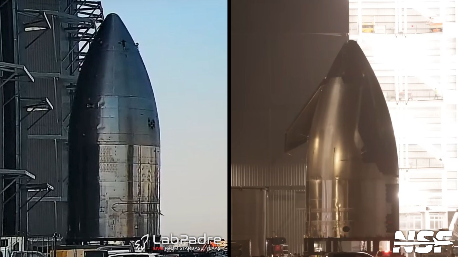
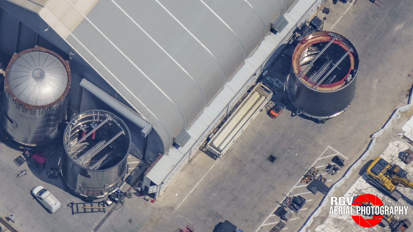
用于先前船舶设计(左)和升级后的船舶设计(右)的组装鼻锥和有效载荷堆栈。 | 照片由 LabPadre Rover 1(左)和 NASASpaceflight 的 Jack Beyer(右)提供
SpaceX claims the new ship prototype can carry over 100 metric tons to low Earth orbit, although this is likely only true when paired with the upgraded Super Heavy booster, which will not be present initially.
SpaceX 声称新飞船原型可以将超过 100 公吨的重量运送到近地轨道,尽管这可能只有在与升级后的 Super Heavy 助推器配对时才成立,而升级后的 Super Heavy 助推器最初不会出现。
Elon Musk, CEO of the company, has previously stated that the third flight test, featuring Ship 28 and Booster 10, was capable of carrying 40 to 50 metric tons to orbit.
该公司首席执行官埃隆·马斯克 (Elon Musk) 此前曾表示,以 28 号船和 Booster 10 为特色的第三次飞行测试能够将 40 至 50 公吨的重量送入轨道。
Currently, flight three would be around 40 or 50 tons to orbit, so the current design.
目前,第三次飞行的轨道重量约为 40 或 50 吨,因此目前的设计。
-- SpaceX 首席执行官埃隆·马斯克,2024 年 4 月星际飞船演示,2024 年 4 月 4 日
This number, which is significantly lower than SpaceX's initial estimations, was likely impacted by the reduced propellant load for that flight and the dry mass of the vehicles. The upgraded ship likely addresses many of the design-related concerns.
这个数字明显低于 SpaceX 的初步估计,可能是受到该次飞行的推进剂负载减少和飞行器干质量的影响。升级后的飞船可能解决了许多与设计相关的问题。
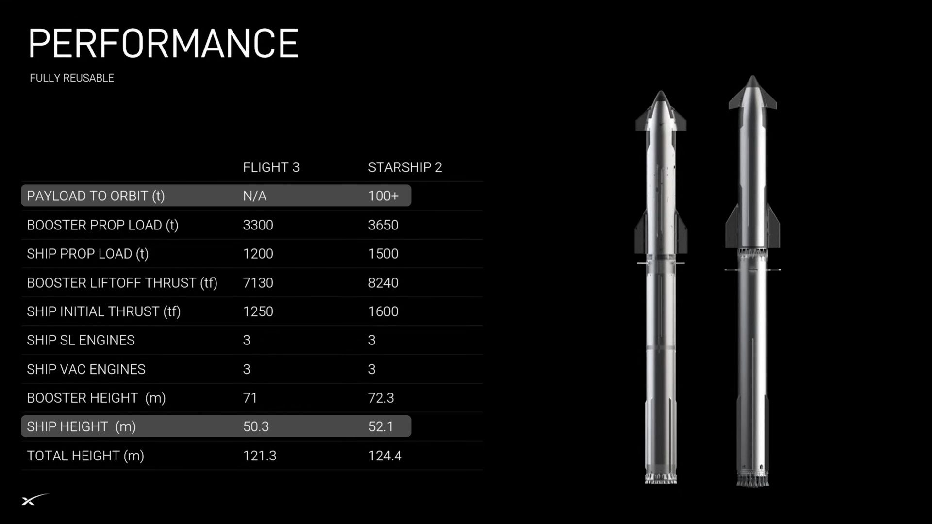
官方规格列表,其中突出显示了 Starship 版本之间的高度和有效载荷能力。|图表由 SpaceX 提供
Smaller Payload Volume 更小的有效载荷体积
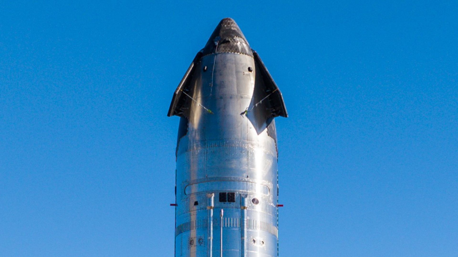
Starship's cargo area is composed of three main sections: the nosecone, payload bay, and forward dome. Together, they create an enclosed volume to protect payloads and auxiliary hardware during the harsh ascent and descent phases of flight.
Starship 的货物区由三个主要部分组成:前锥、有效载荷舱和前圆顶。它们共同创造了一个封闭的体积,以在飞行的艰难上升和下降阶段保护有效载荷和辅助硬件。
As discussed in our nosecone article, the tapered nosecone structure is the same shape and size between the two versions of the ship, however, the internal structure has been changed to utilize low-profile internal stringers that greatly reduce the impingement on the payload volume.
For the previous ship design's payload systems, the entire nosecone went unused, as the large flap frames reduced the diameter of the payload volume and made it impossible for the Starlink satellites to enter the upper area.
As a result of these changes on the newer ships, the lower half of the nosecone has largely been opened up for cargo use.
While it is desirable to be efficient with the tapered portion of the cargo area, the cylindrical portion of any payload fairing is by far the most useful since it has a uniform diameter.
For the latest Starships preceding Ship 33, the payload barrel was a five-ring section that stood just over nine meters in height. Most payload-related equipment, including the actuated door and satellite dispenser, were exclusively found in this segment.
By making this a five-ring barrel section, SpaceX was able to preinstall several large components before integration with the vehicle, namely, the Starlink PEZ dispenser. At the time, this was the largest barrel section found on the ship.
Contrasting this, the new payload barrel is a mere three rings tall, standing at roughly 5.5 meters in height. It still houses payload-related equipment and now also has the raceway connections, the access hatch, and other hardware that was previously found on the forward dome section.
Reducing this to a three-ring barrel section obviously results in the cargo area being smaller, and it also means that less hardware is exclusively confined to the cylindrical barrel.
It is likely that when SpaceX extends the payload bay in the future, they will simply make this barrel section taller.
The next part will be familiar if you have already read our upgraded tanks article.
The forward dome section, found at the bottom of the payload bay, is exactly what it sounds like. This barrel features the forward bulkhead of the liquid methane tank, which also acts as the bottom "floor" of the payload bay.
On previous ships, this was a three-ring barrel with the dome located near the middle of the centermost ring, as indicated by the horizontal weld markings. This meant that about 1.5 rings served as part of the payload bay in addition to the five-ring barrel.
Since this portion of the payload bay is below the top of the forward bulkhead, it is unusable for payloads. Regardless, it is still useful for other pieces of vehicle hardware.
The new forward dome section is a four-ring barrel section with the dome shifted to the bottom of the uppermost ring.
This means that less of this barrel is allocated to the payload compartment, as the unpressurized area occupies less than one ring. It also means that the "unusable" volume at the bottom of the payload bay is much smaller compared to before.
So, let's recap.
Due to its updated reinforcements, the lower portion of the nosecone is now an accessible part of the payload volume, which was not the case on the older ships. What was essentially a gigantic dead space is now useful and can be filled. This is really the key change.
The new payload bay, while shorter compared to the older version, benefits from the newly accessible space in the nosecone, essentially bringing it back to the same height as the old barrel section. The taper on the nosecone's lower half is so small that it can be used for most things, including Starlink satellites.
With the implementation of the flatter domes, the forward dome section now has less dead space adjacent to the bulkhead, packing everything tighter together.
If you've noticed a theme here, you're not wrong. Everything related to the new payload bay is about deleting dead space. While, yes, the new payload bay is technically smaller, the areas that SpaceX has deleted weren't being used to begin with. Since SpaceX really only utilized the cylindrical area on the older ship design, the new payload bay is roughly that size.
It's actually slightly larger.

Additional Reinforcements
The ship's payload bay is not pressurized to the degree of the tanks, so while it retains some pressure during ascent, it still needs extra reinforcements to prevent it from buckling. SpaceX has yet again increased the number of vertical stringers inside the payload bay, further strengthening the barrel section against axial loads.
With a small door, we can use pressure stabilization, like, we can retain pressure in the fairing, so we can at least partially pressure stabilize the nosecone, or fairing. And then we don't have a humongous hinged door.
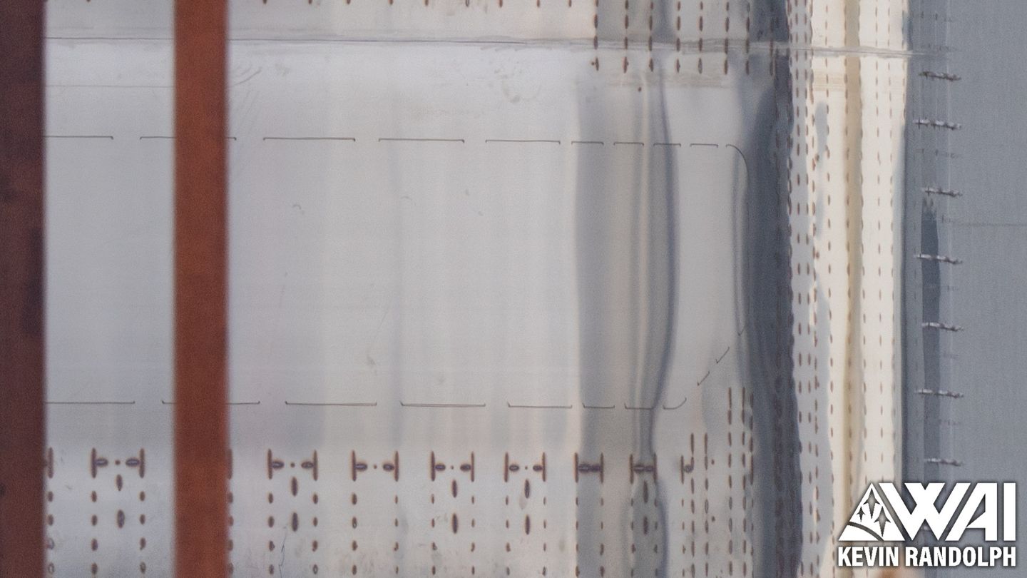
On Ships 25 to 32, there were approximately 96 columns of internal stringers found inside the payload bay. Not all of these continued to the top of the barrel, as fewer internal stringers were situated above the payload door.
Also notice how the stringers were perforated on the faces, similar to the stringers inside the ship's tanks.
For the new design, there are approximately 120 columns of internal stringers, which again follow the same pattern. Just like the older design, there aren't many found above the door itself.
Additionally, all of these stringers have solid faces, which is an interesting deviation from the previous design.
Since these match the arrangement of these stringers in the upgraded nosecone, couplers are added between them. As a result of this, there is now a single structure running from the top of the payload bay to the bottom with no interruptions.
Internal Frame Structure
The previous ship design had several internal hoop stiffeners distributed across the length of the payload bay section, radially reinforcing the barrel. Some of these were seemingly related to the PEZ dispenser, as many were omitted on Ship 26.
The PEZ dispenser also had semicircular frame pieces on its sides, which were attached to the walls of the ship and kept the dispenser frame rigid. Since there were several stacks of Starlinks indexed within these frames, any significant movement could cause binding in the system.

The new payload bay appears to have a single hoop stiffener across the middle, but there are some other fascinating supports that should be discussed.
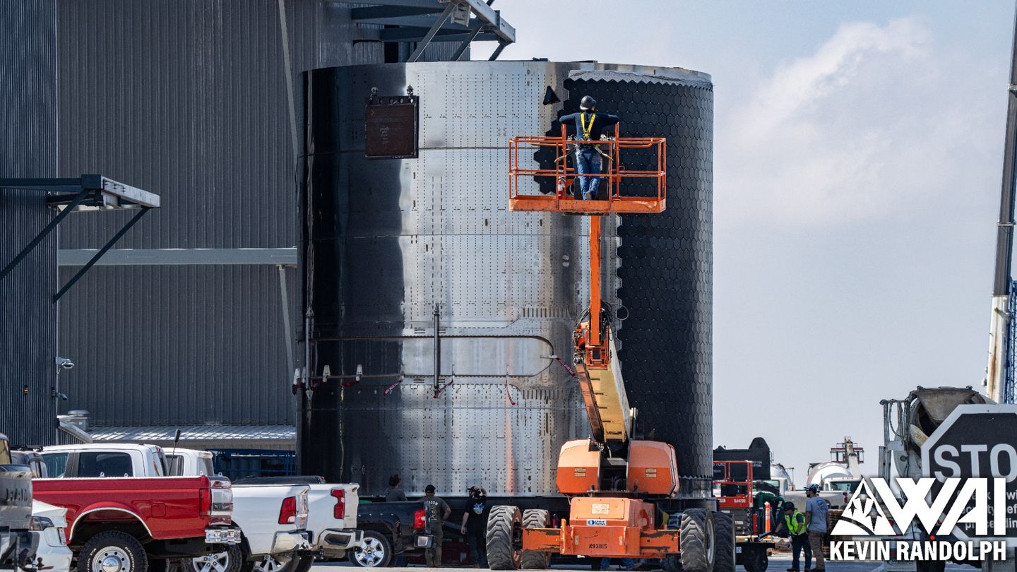
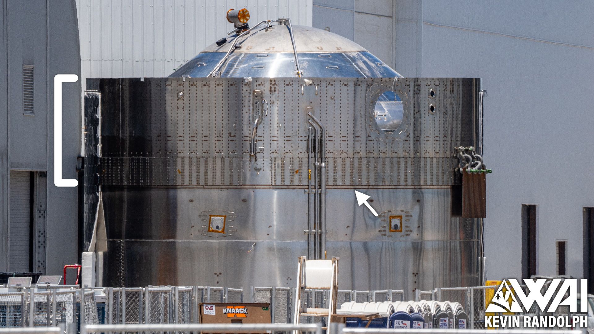
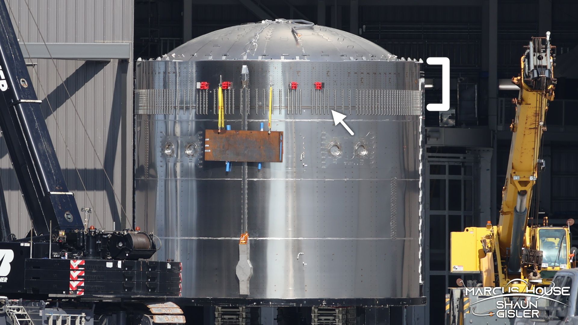
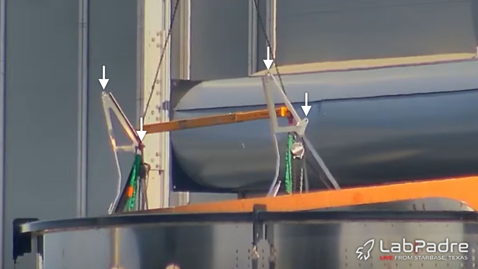
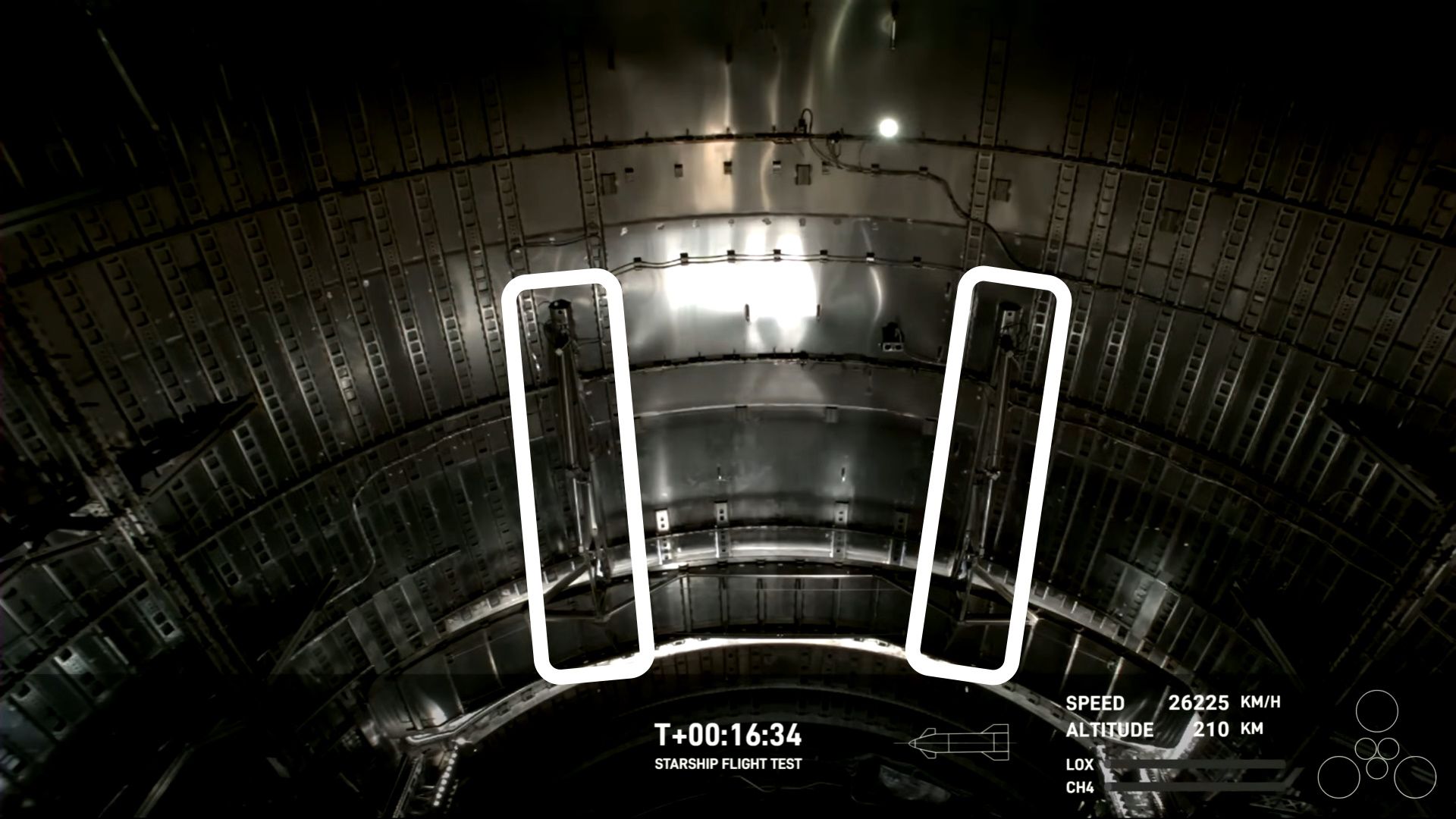
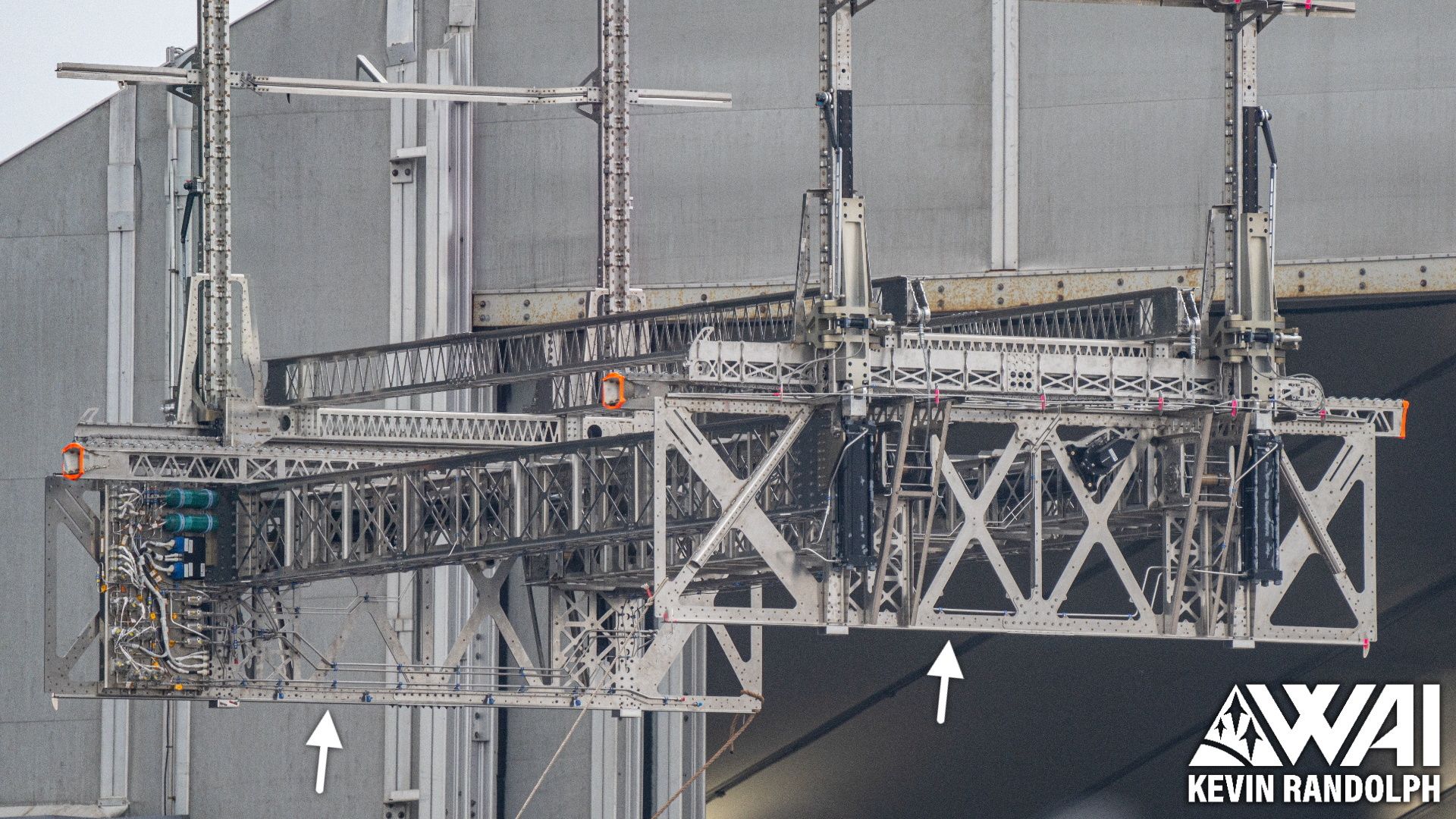
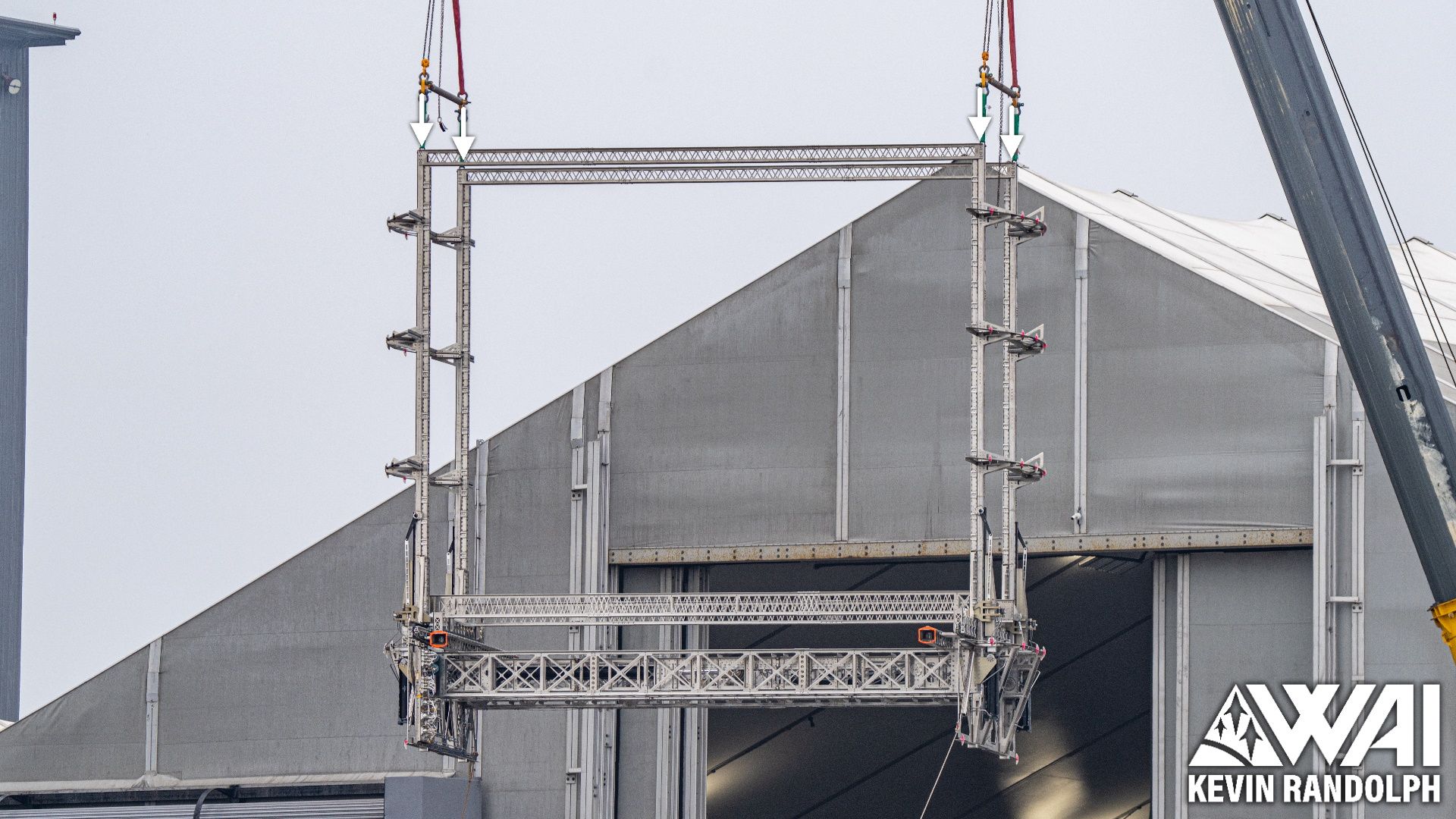
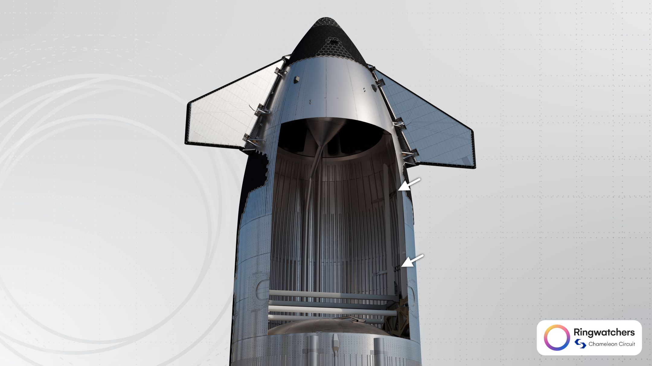
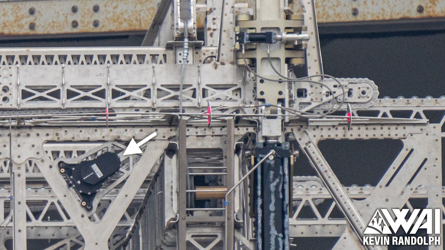
Weld markings indicate the presence of horizontal frames on the left and right sides of the payload bay, and we can even see one through the doorway. These frames have prominent welds on the ship's exterior and are indicated with arrows in the following annotated image.
Another pair, as you may recall, is found inside the ship's nosecone. This was mentioned all the way back at the beginning of this article series, so it may be difficult to recall.
It isn't exactly clear if these frames function as radial supports for the payload bay, but we do know that they are directly related to the PEZ dispenser, replacing the old semicircular frames.
We'll come back to these later.

Lifting Sockets
The lifting sockets, which are the primary thing that the upgraded ship is lifted by, have been relocated to the payload bay on the upgraded ship design, and the payload bay has been reinforced to accommodate this relocation.
It's unclear if these are connected to the horizontal frames mentioned in the previous section, but it is certainly possible due to their proximity to each other.
There is also a large rhombus-shaped doubler plate around each of the sockets, bracing the surrounding area. The heat shield is partially concealing this doubler in the following image.
Notice the circular cutouts in a repeating triangular pattern, which are able to slot overtop of the tile attachment pins on the windward side. Since these are present, the doubler plates do not interfere with the heat shield.
Part XI - Sliding PEZ Door
As a reusable launch vehicle, Starship requires a payload door that can be opened and closed repeatedly rather than a single-use deployable fairing. The PEZ dispenser system is a Starlink-specific design that allows the flat satellites to be deployed in sequence, removing the need for a larger payload door.
The PEZ door appears to be fundamentally similar between both generations of the ship, however, it has been upgraded in several ways. Starship's third flight test seemingly revealed some issues with the door, so SpaceX's iterative method is in action once again as they revise and fix the design ahead of operational launches.
[Flight 3's door test] had some issues.
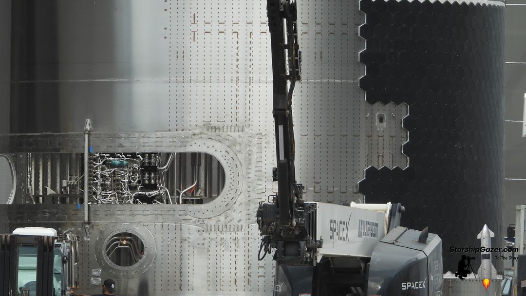
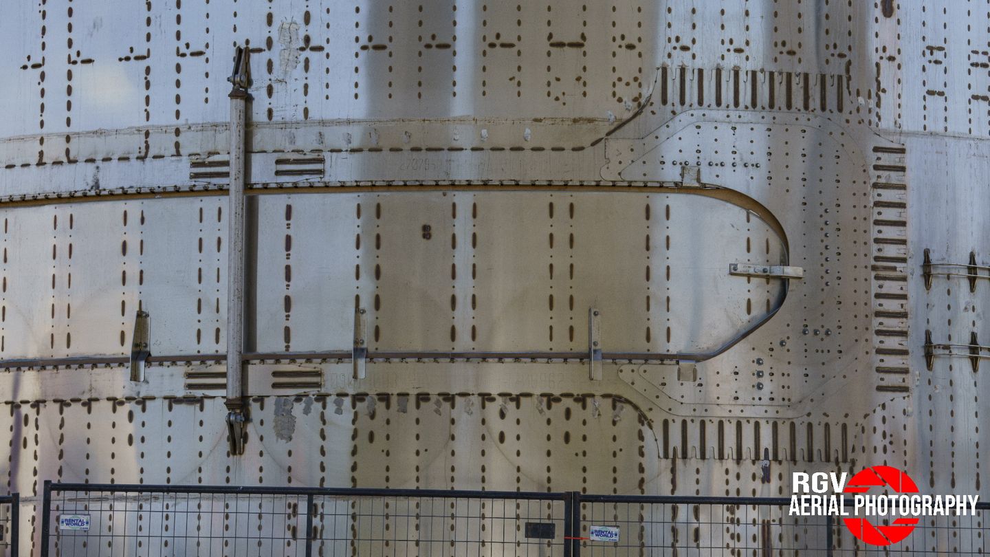
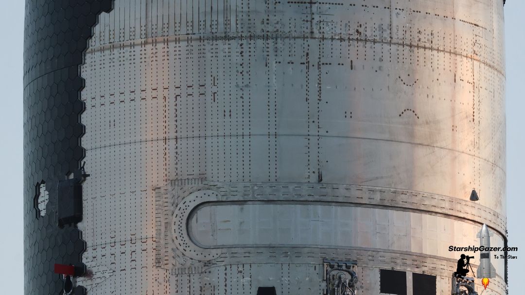
Updated Door Hole
On the older generation of ships, the PEZ dispenser door was a mostly rectangular cutout with two angled corners. It's not exactly clear why it was shaped this way, but this was the design SpaceX chose and kept using. The structure around this opening went through many revisions during this early period.
Ultimately, the design SpaceX settled on used three layers of doubler plating on either side of the door and a single layer above and below it, ensuring that it would not deflect or warp under flight loads. While this worked, it was not the original design and was implemented to address structural concerns with the payload bay.
Take note of the door cutout's position on the ring, not crossing any ring welds or tricky areas. The position of the door is determined by the position of the PEZ dispenser, which is also determined by the height of the forward dome, which is dependent on the length of the tanks. There are a lot of pieces that need to line up.
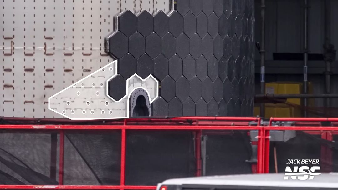
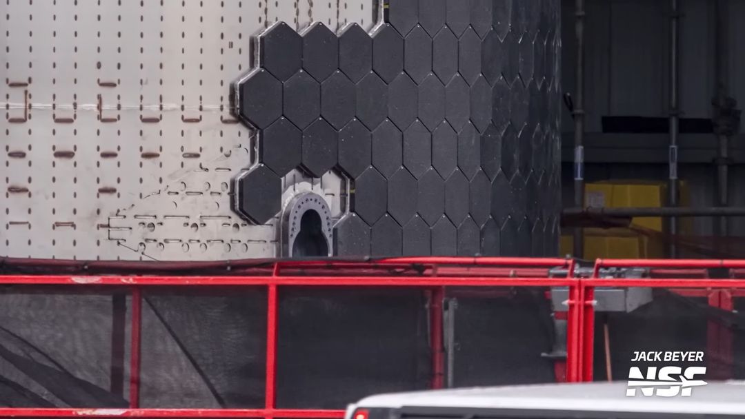
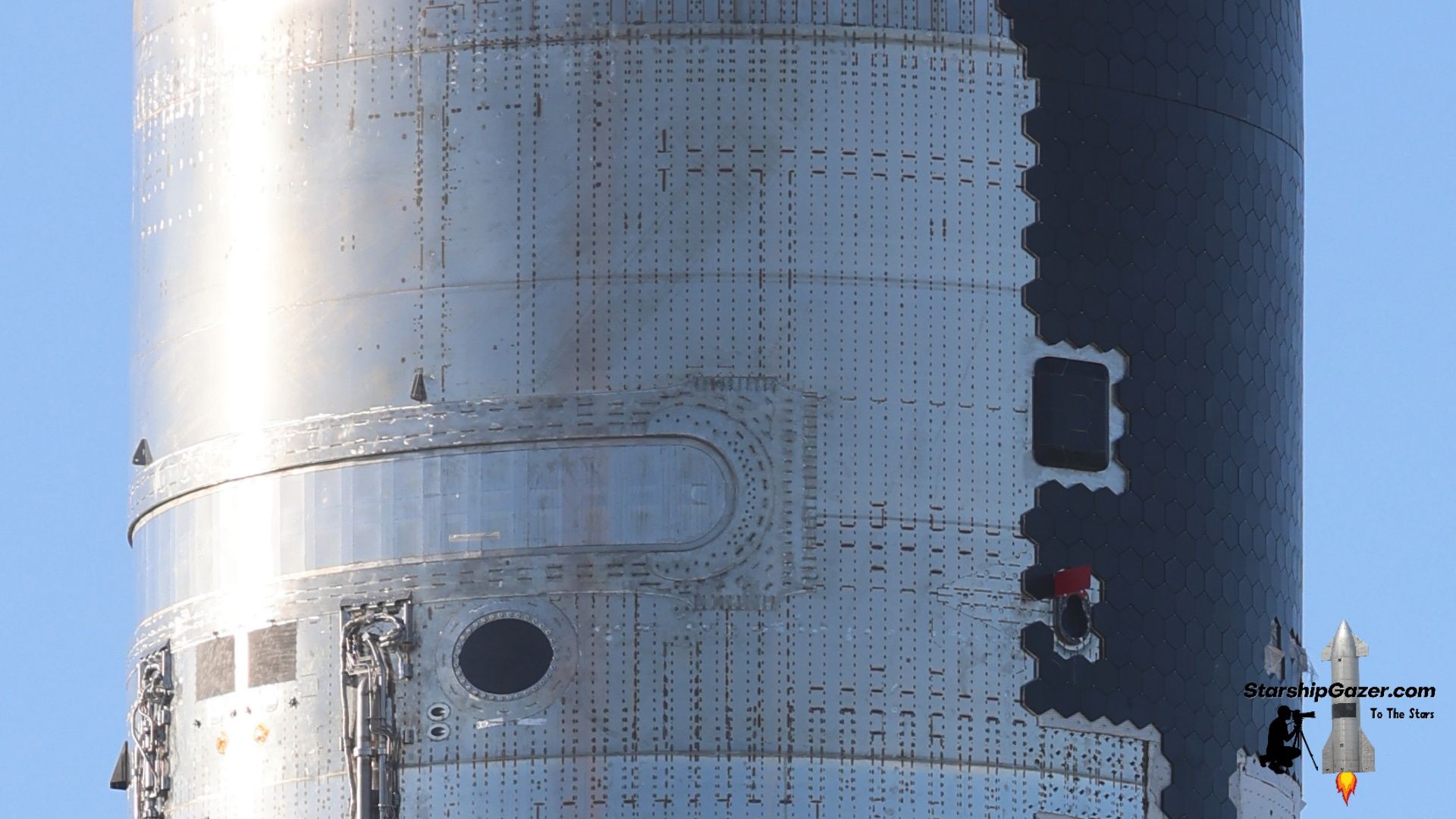
The new design has a completely rounded payload door, which may remove stress points that could have been present in the previous design. It appears to be roughly the same dimensions, or at least, similar enough to not make any meaningful difference.
The doubler plating has also been simplified, with only two layers of plates on the sides and a single layer above and below it. These reinforcements still have a fairly large footprint, but overall have been cleaned up and should be a more efficient design.
The door is also now situated lower on the barrel section, crossing over the weld between two rings. Again, this position is highly dependent on how the various pieces of internal hardware line up.
Updated Door Panel
The sliding door panel, which functions as the actual door inside of the ship, is not a very complicated piece of hardware. Since the PEZ dispenser design does not require the door to be a structural element, this is really just a blocker for the opening in the side of the ship.
The door panel for the previous design had a similar shape to the door cutout, with two angled corners on the bottom. An additional steel layer was added over the perimeter for a seal to interface with.
SpaceX never attempted to open the previous ship design's door in flight again following Ship 28's brief demonstration.
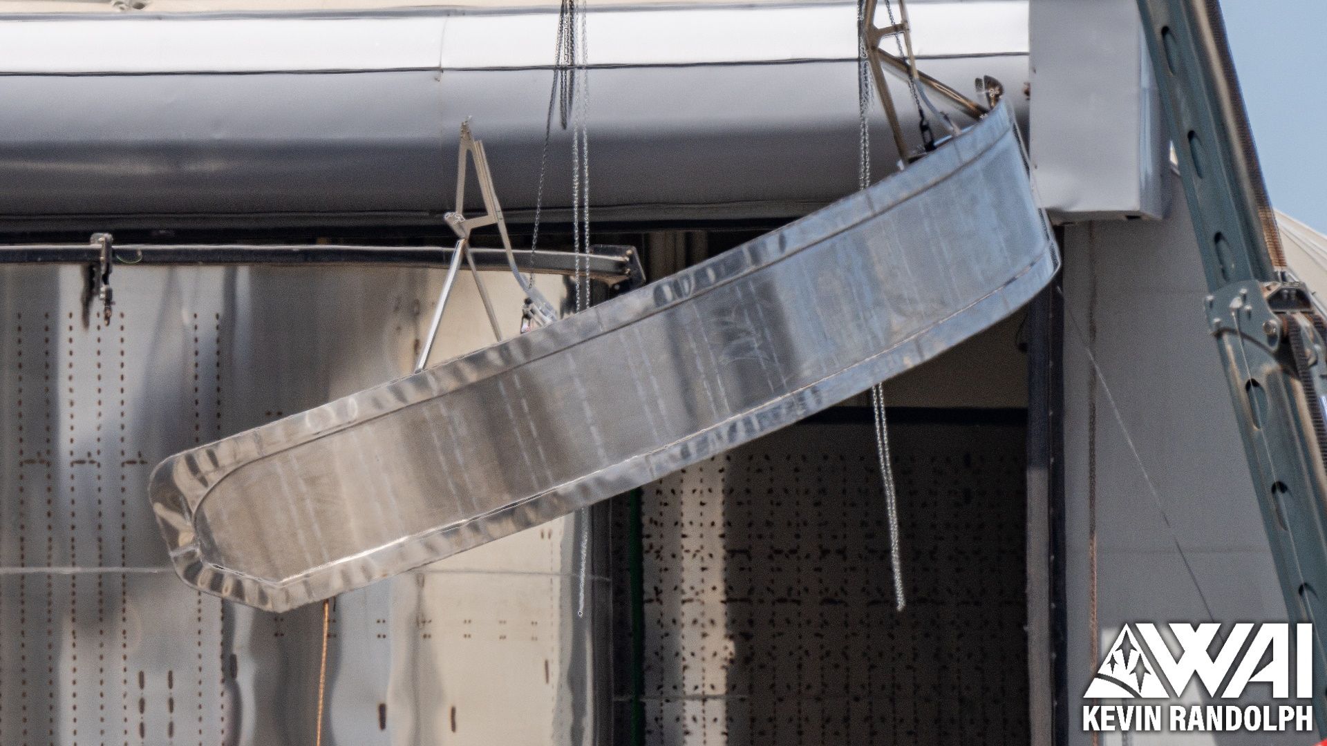
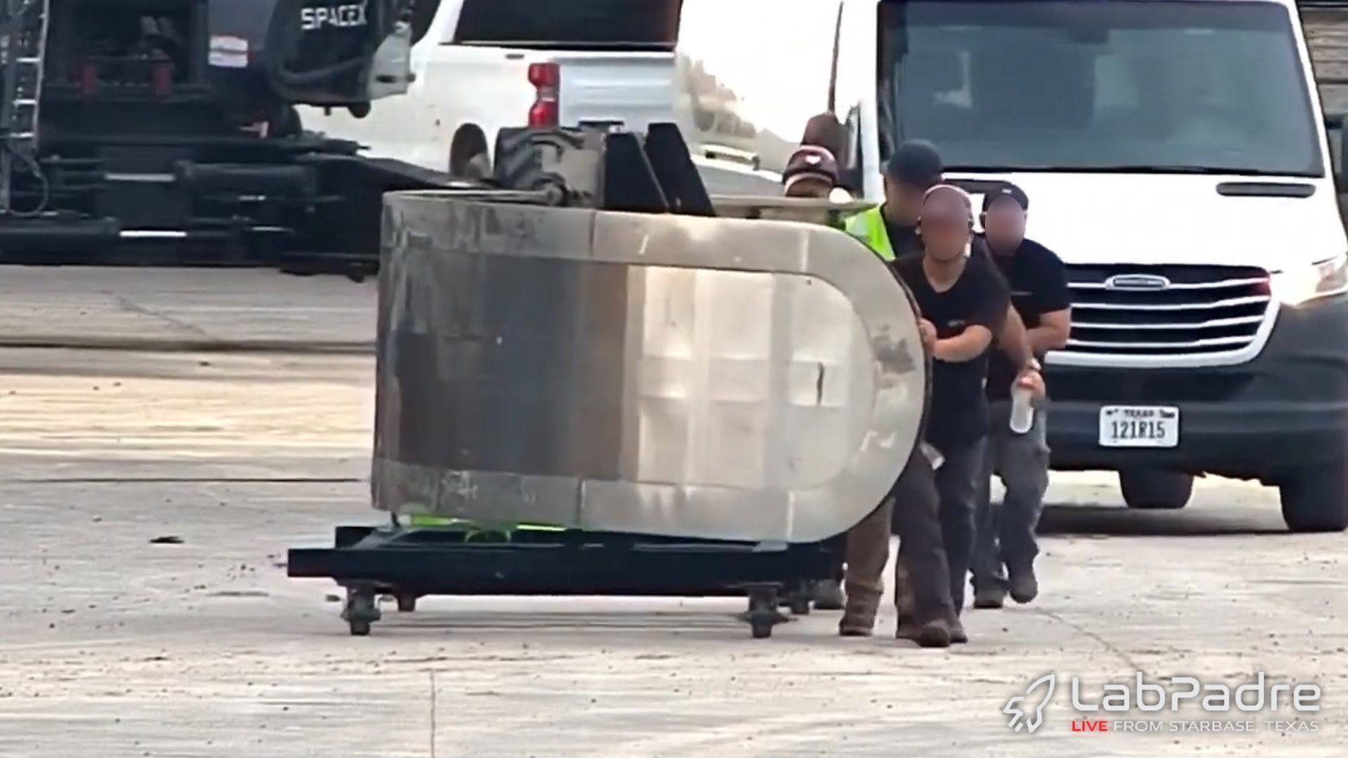
The new design matches its respective door cutout and therefore features completely rounded ends that match the hole in the ship.
Just like the previous design, an additional steel layer is added to the perimeter for the seals to interact with. This may add some rigidity, but it's unclear if that is its true purpose.
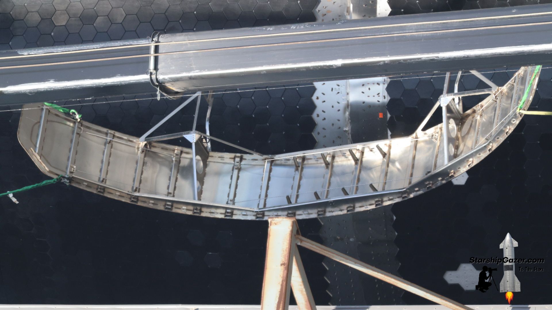
Moving to the interior of the older door, we can immediately notice 20 vertical internal stringers that gave the door extra rigidity, in addition to frame structures on the top and bottom of the door.
These angular frames ensured that the curve of the door matched that of the ship. If there was deformation, the door would likely not seal as intended.
In some areas, we can see tensioned cables that also helped the door maintain its shape, working alongside the frame structures on the top and bottom.
The new design is fundamentally similar but has a few major differences.
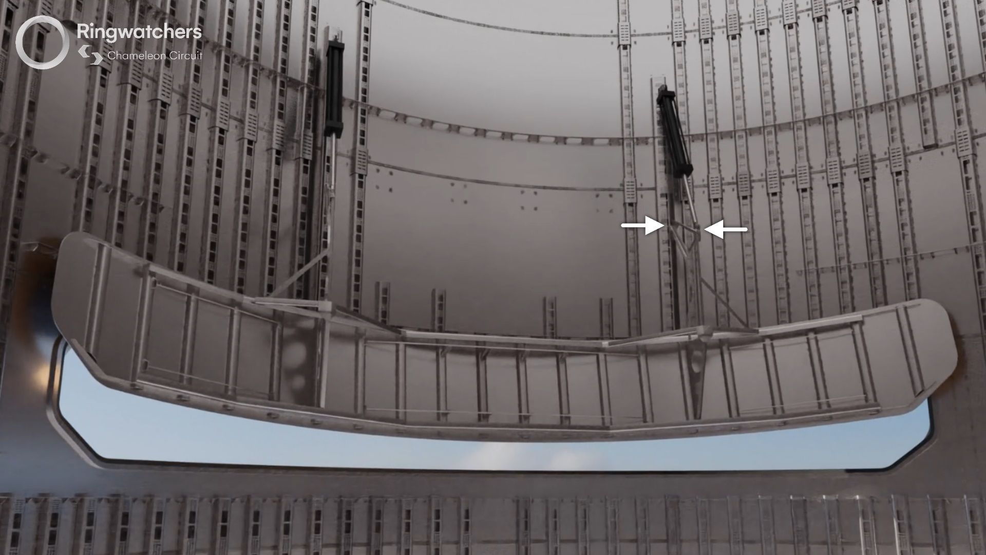
Firstly, notice the vertical stringers on the interior of the door, similar to the previous design, There now appear to be 23 internal stringers, axially strengthening the door panel.
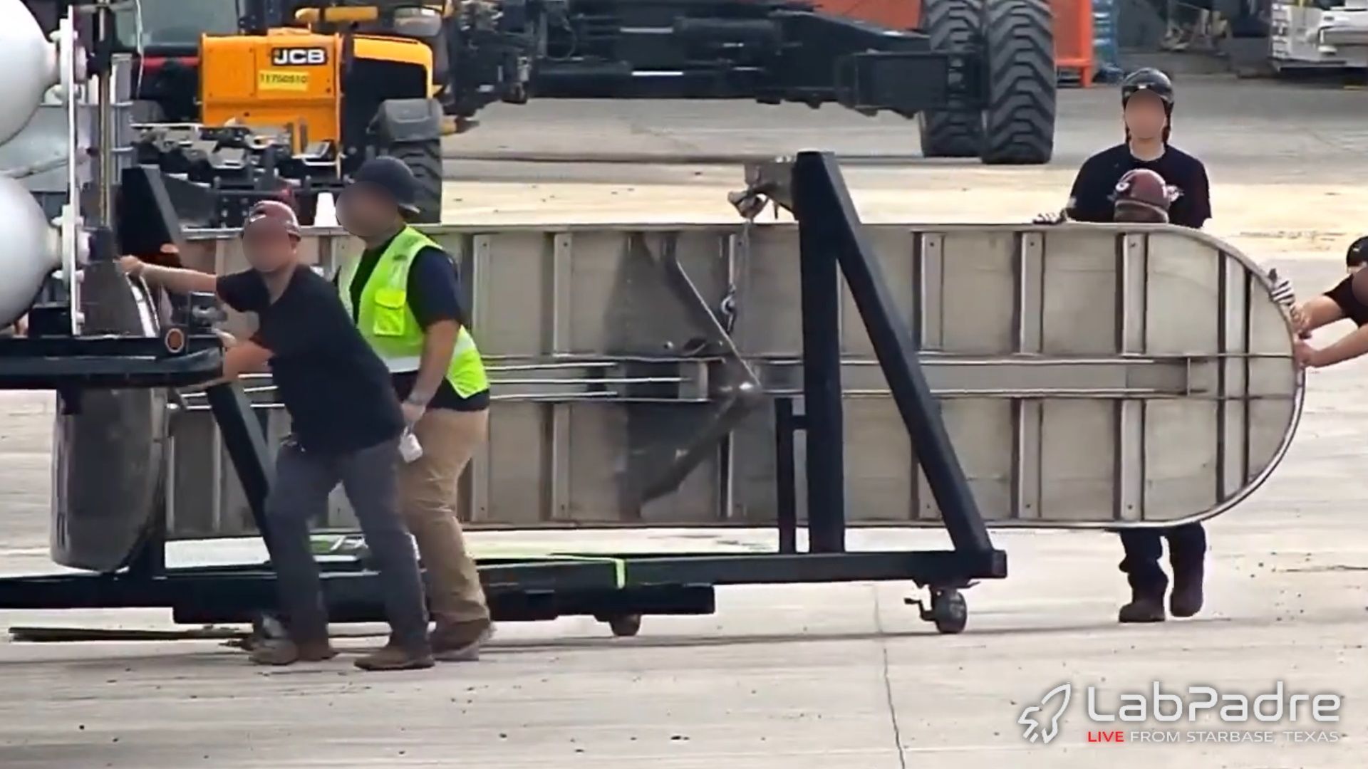
There is also now a frame component at the door's midpoint, running across the entire width of the door. This frame likely serves the same purpose as the frames on the top and bottom of the previous design, ensuring that the door does not become deformed.
Similar cables appear to be present inside this frame, ensuring that the door does not deform. Without these, it is essentially just a flat and flimsy piece of steel.
An additional frame is also now found on the perimeter of the door, which should assist with keeping the panel rigid. This was not present at all for the original door design.
Overall, the door is strengthened very similarly to the older design but generally seems to be a bit bulkier. It's possible that this is related to Ship 28's "observation", but it is hard to be certain.
Since the design of this door is largely unchanged, it seems that SpaceX is still confident that the concept behind the PEZ system is sound and simply needs refinement. Hopefully we see this successfully tested soon, setting the stage for the first launch of Starlink V3 satellites.
Actuation System
The actuation system for the PEZ door allows it to open and close when commanded and is one of the most important parts of the entire payload deployment system. It allows the door to... door.
For the previous design, two large lifting arms were attached to the interior face of the door, with two attachment points on each. The upper attachment points would connect to a rail system for the door to slide on, while the lower points would connect to the pistons that moved the door.
Pistons on the ship's interior connected to these attachments and pulled upwards to open the door. These pistons were situated at the top of the door's rail structures, which were the pieces that the door slid inside.
As the pistons pulled up on the door's lower attachments, it would tilt inwards, pivoting on the upper attachments. This depressed the seal and the door would then begin sliding up, clearing the doorway ahead of Starlink deployment.
In this image, we can see the actual rail and piston assemblies inside Ship 28. These rails could be identified via prominent external weld markings that resembled large stringers.
As for our analysis of the upgraded actuation system, there isn't much that we can actually discern and compare due to a lack of imagery. As such, we cannot say how similar or different this design is.
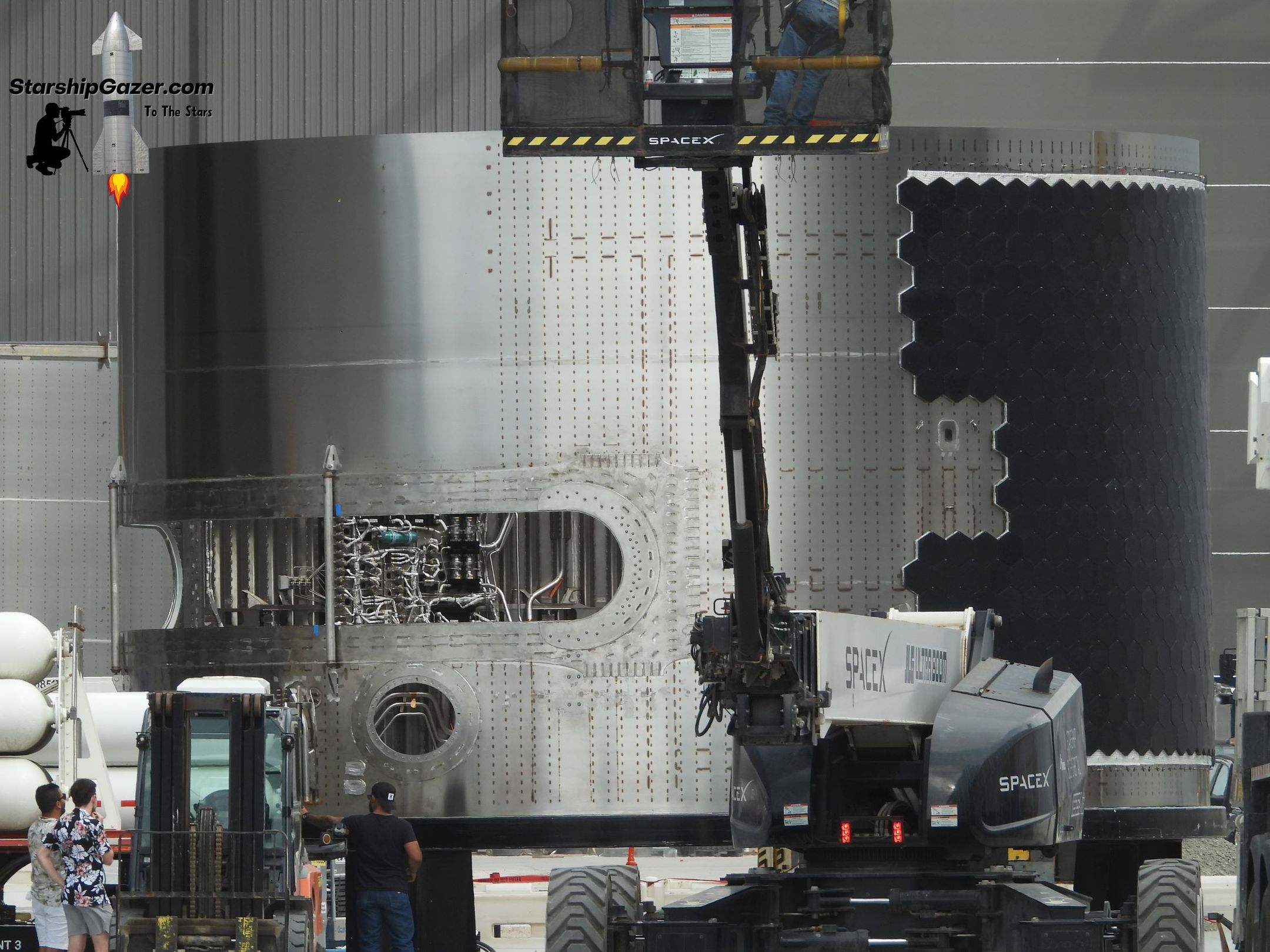
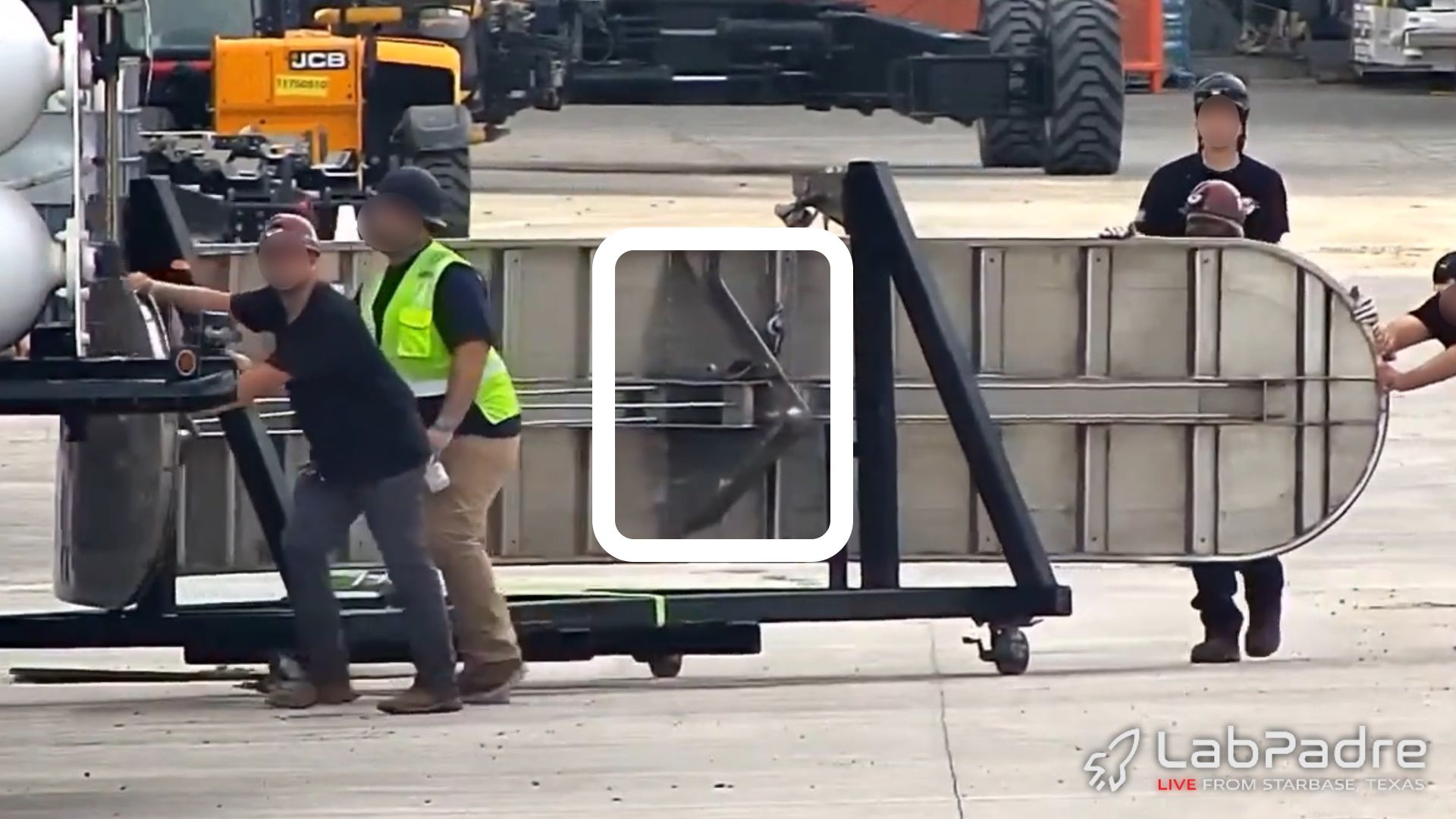
Our only image of a payload door for the upgraded ship does not have the two lifting arms that connect to the actuation system. The transport frame is connected to where these lifting arms would eventually attach, and as such, we do not know what these arms look like.
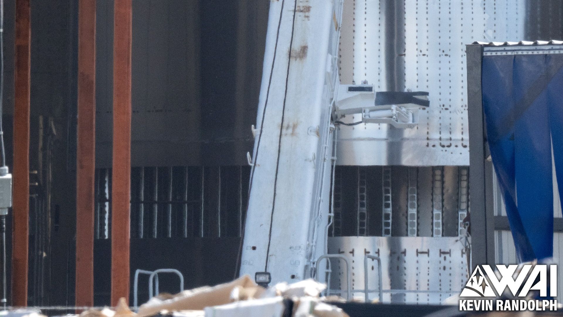
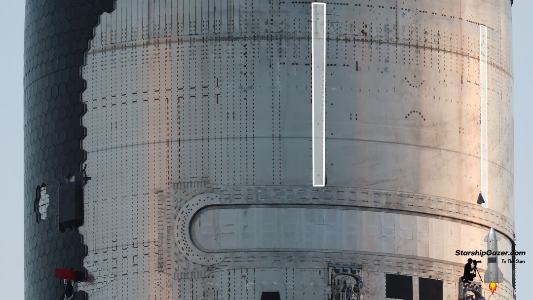
On the exterior of the ship, we can see the weld markings indicating the presence of rails for the payload door. These are in the same position as the previous design and don't appear that different.
The rail structures have very likely been updated to be a stronger and bulkier design, assuming that was part of the issue on the third flight test.
It isn't exactly clear what kind of pistons were used for the previous ship design's door, but it is also extremely likely that the new design has an electric actuation system over any alternatives. This is a major theme for the new payload systems and will come back momentarily.
Part XII - The PEZ Dispenser
The PEZ dispenser is Starship's payload adapter for Starlink V3, enabling the ship to carry a large number of these flat satellites to low Earth orbit. Before Ship 33, there were two variants of the PEZ dispenser, neither of which was ever used in flight.
The first was a subscale dispenser used inside Ships 24 and 25, giving Starship the initial capability to carry Starlinks. An extended version debuted on Ship 27 and was used on all subsequent vehicles. At the time of assembly, SpaceX likely expected to be delivering payloads to orbit with these later vehicles.
The brand new PEZ dispenser appears to have been completely redesigned from a clean slate, however, we believe it is similar in principle. With the ability to hold approximately 54 Starlink V3 satellites, SpaceX's third attempt at a dispenser system is a much cleaner design.

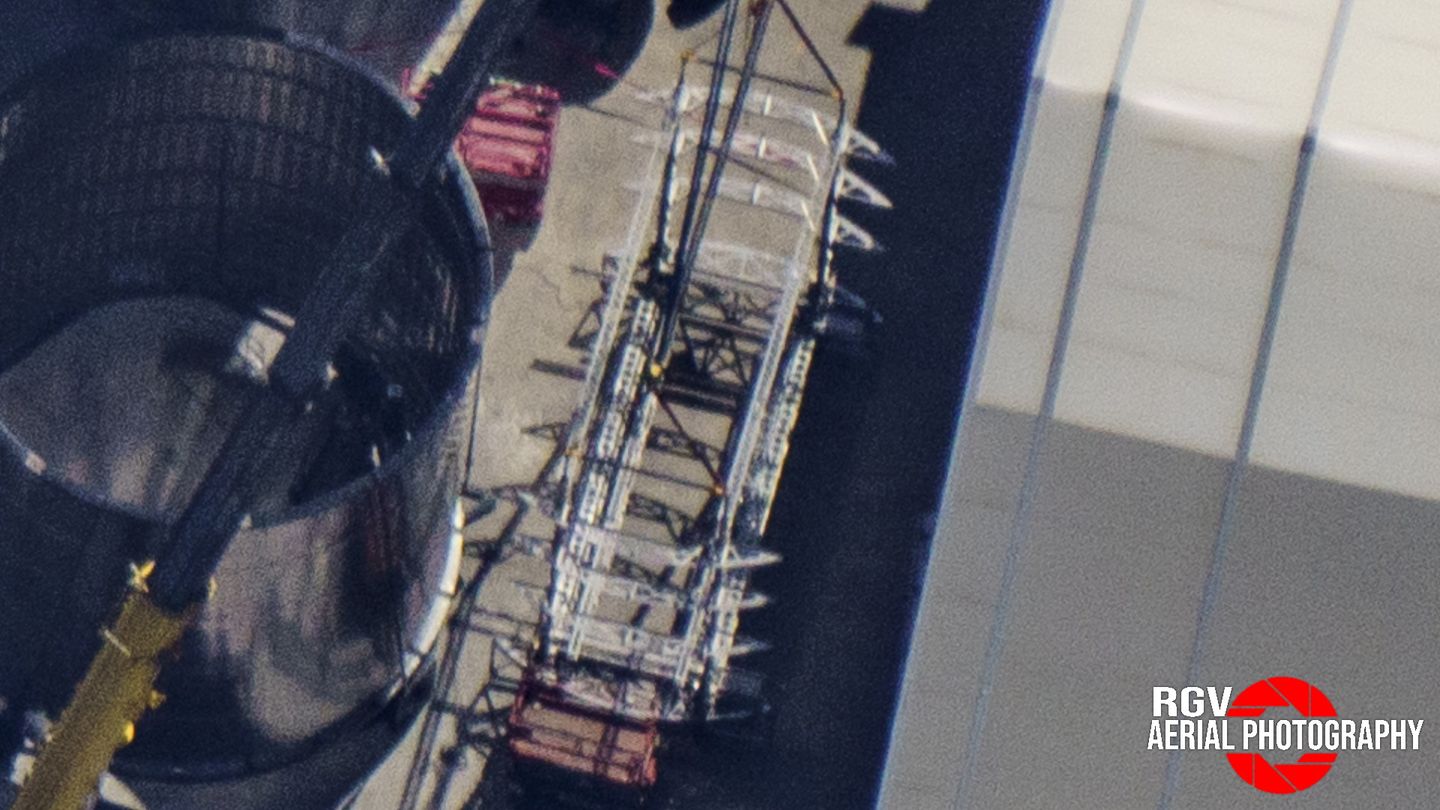
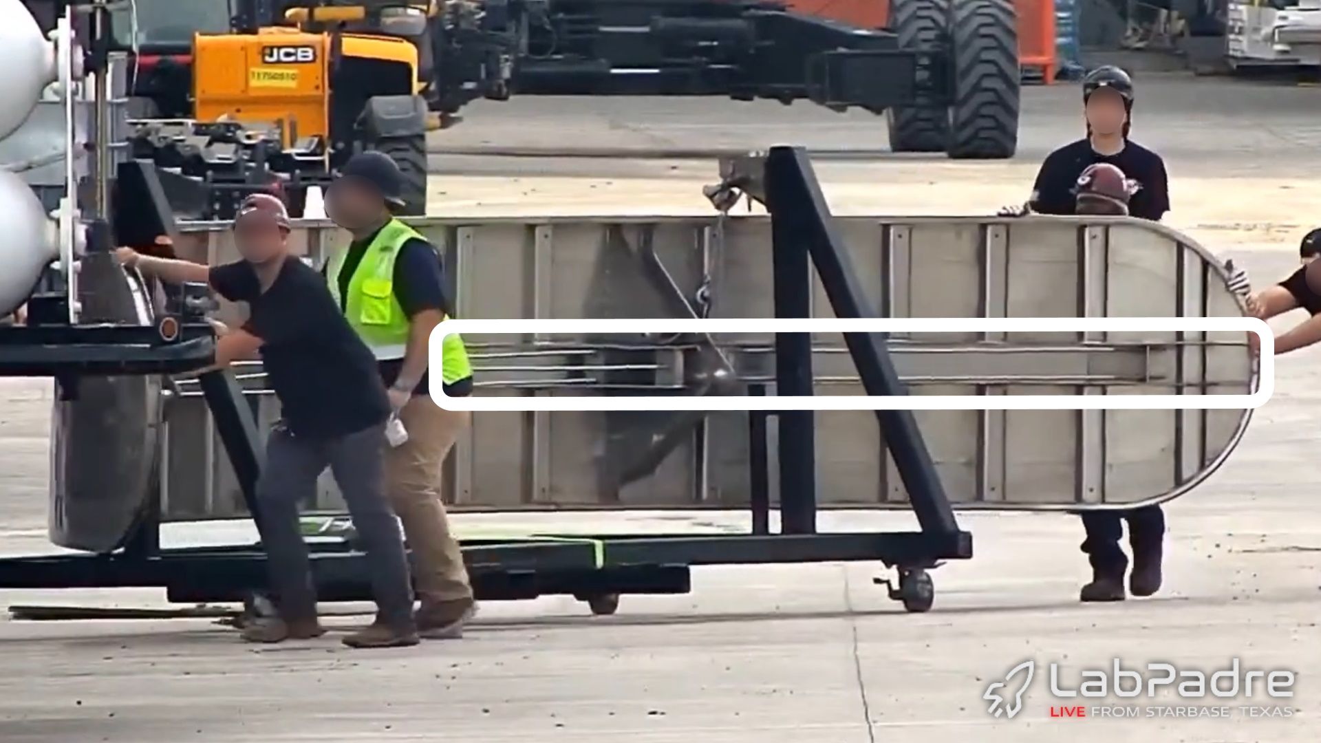
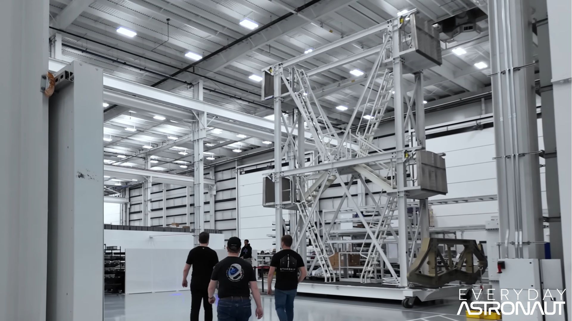
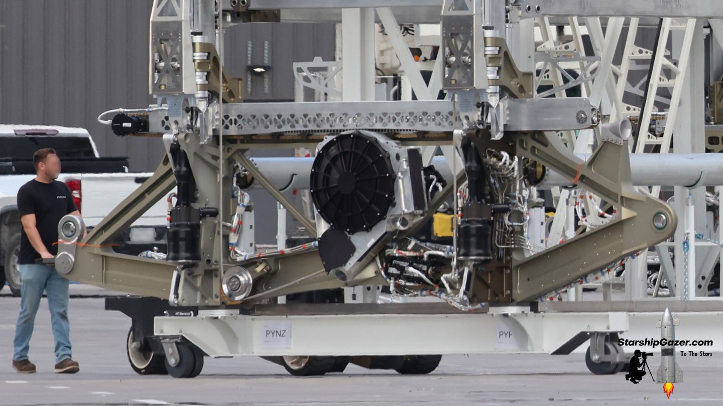
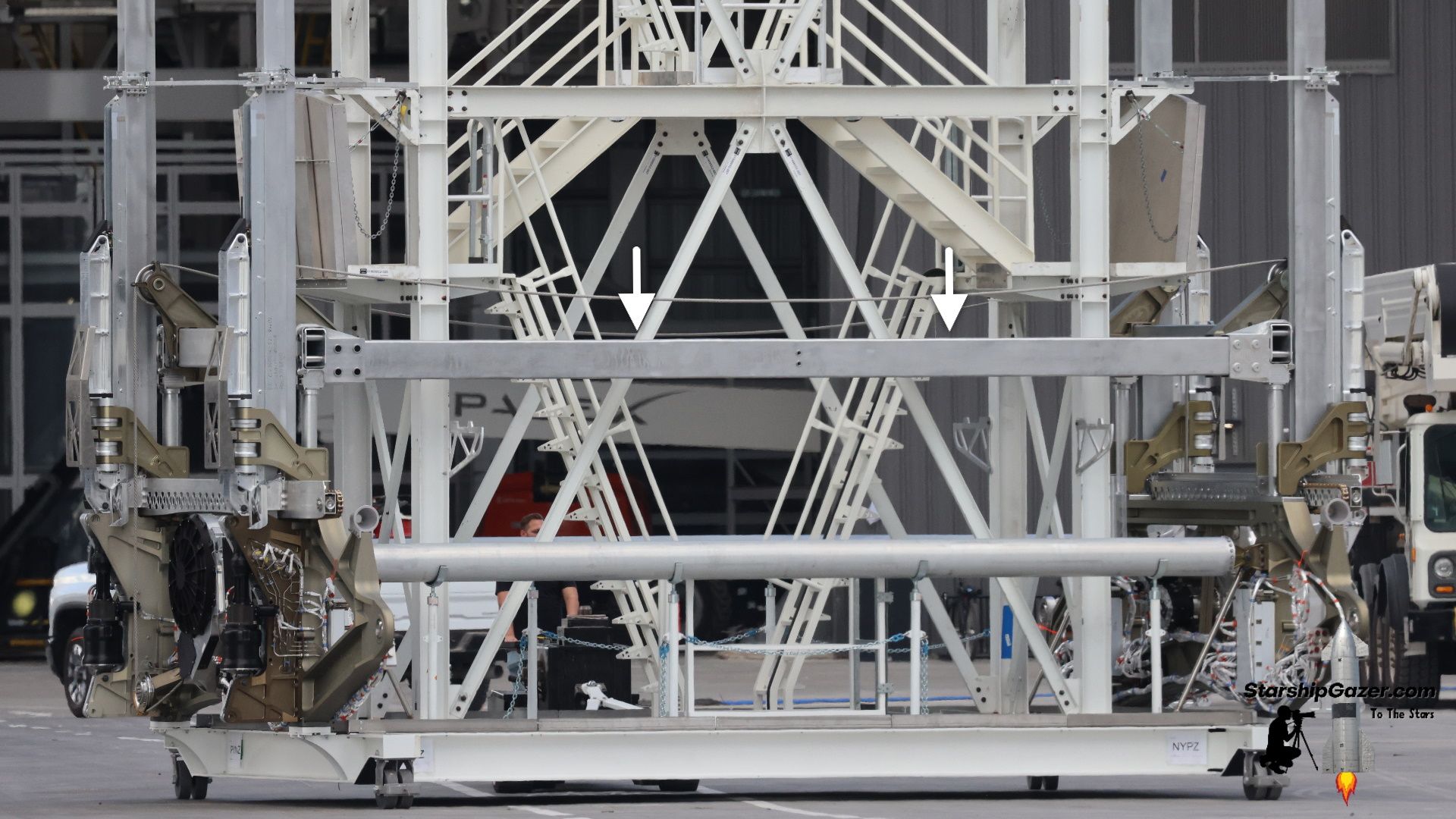
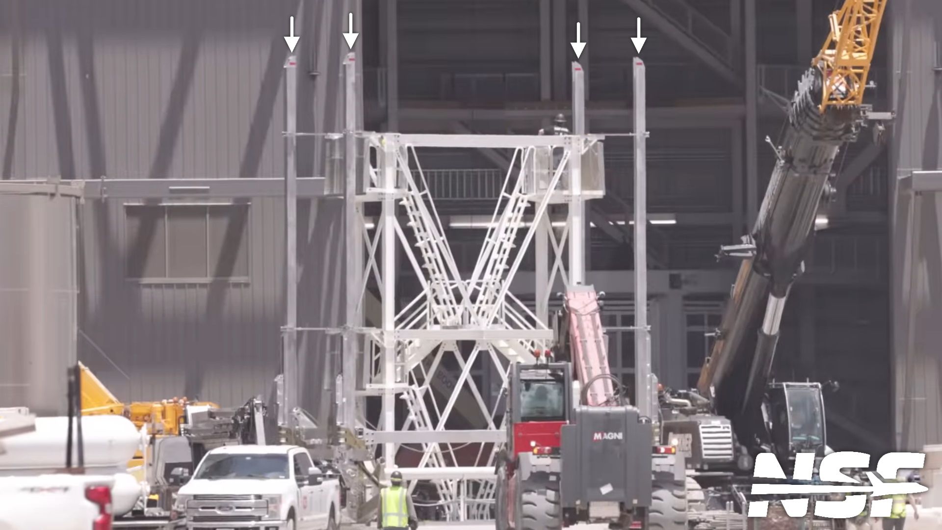
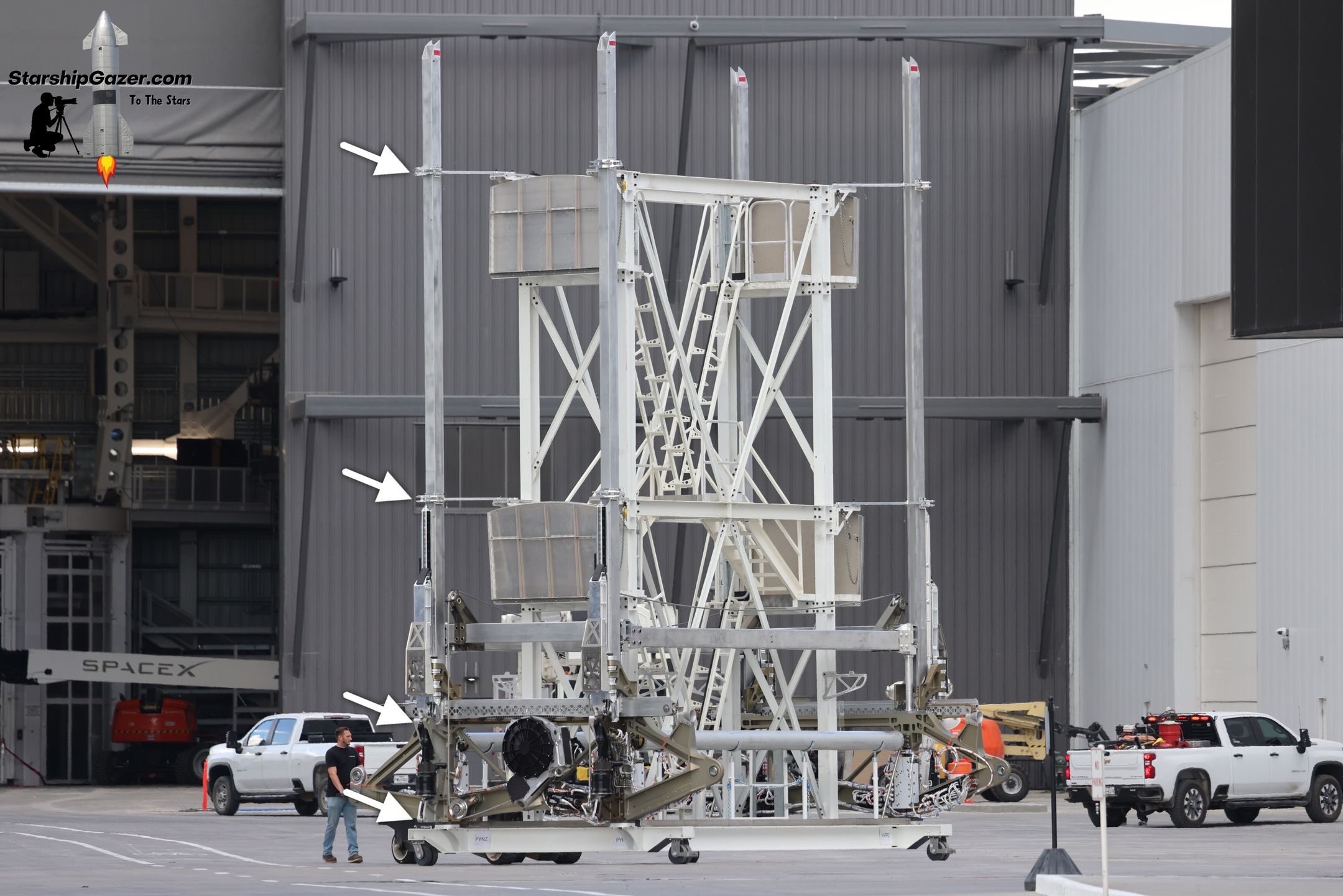
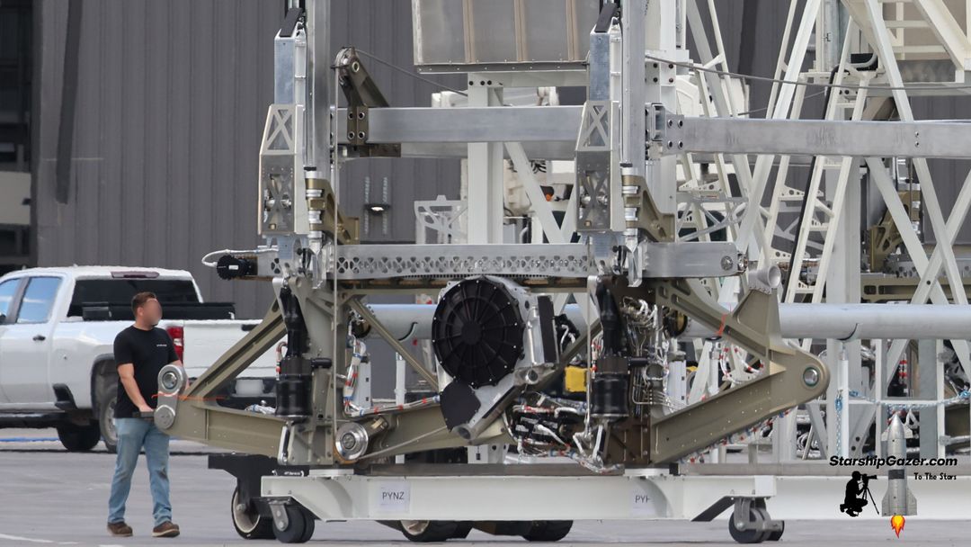
Be advised that the upgraded PEZ dispenser is often photographed on an assembly platform, which is a large white structure with access platforms and staircases. This structure does not remain inside the ship and is only used during the assembly and installation of the dispenser.
The parts painted white are the assembly stand, whereas the silver and gold parts are the actual dispenser.
Dispenser Structure & Capacity
The original Starlink dispenser, found on previous prototypes, was constructed from several stainless steel pieces with triangular cutouts all over them. These pieces, which were either welded or bolted together, formed the dispenser's primary structure.
Several components formed the base for both the old and new designs, so we'll go through each of them, starting with the older design.
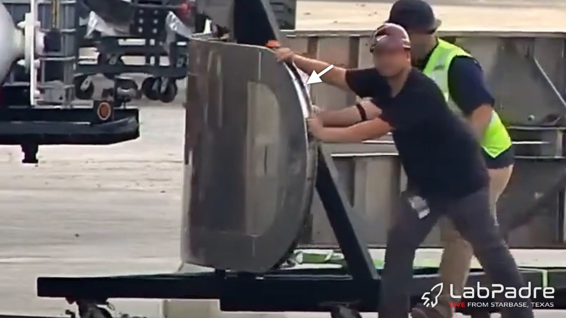
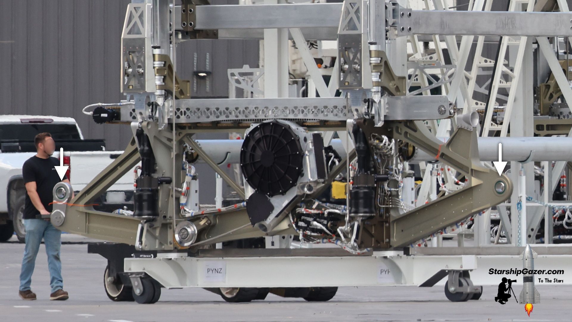
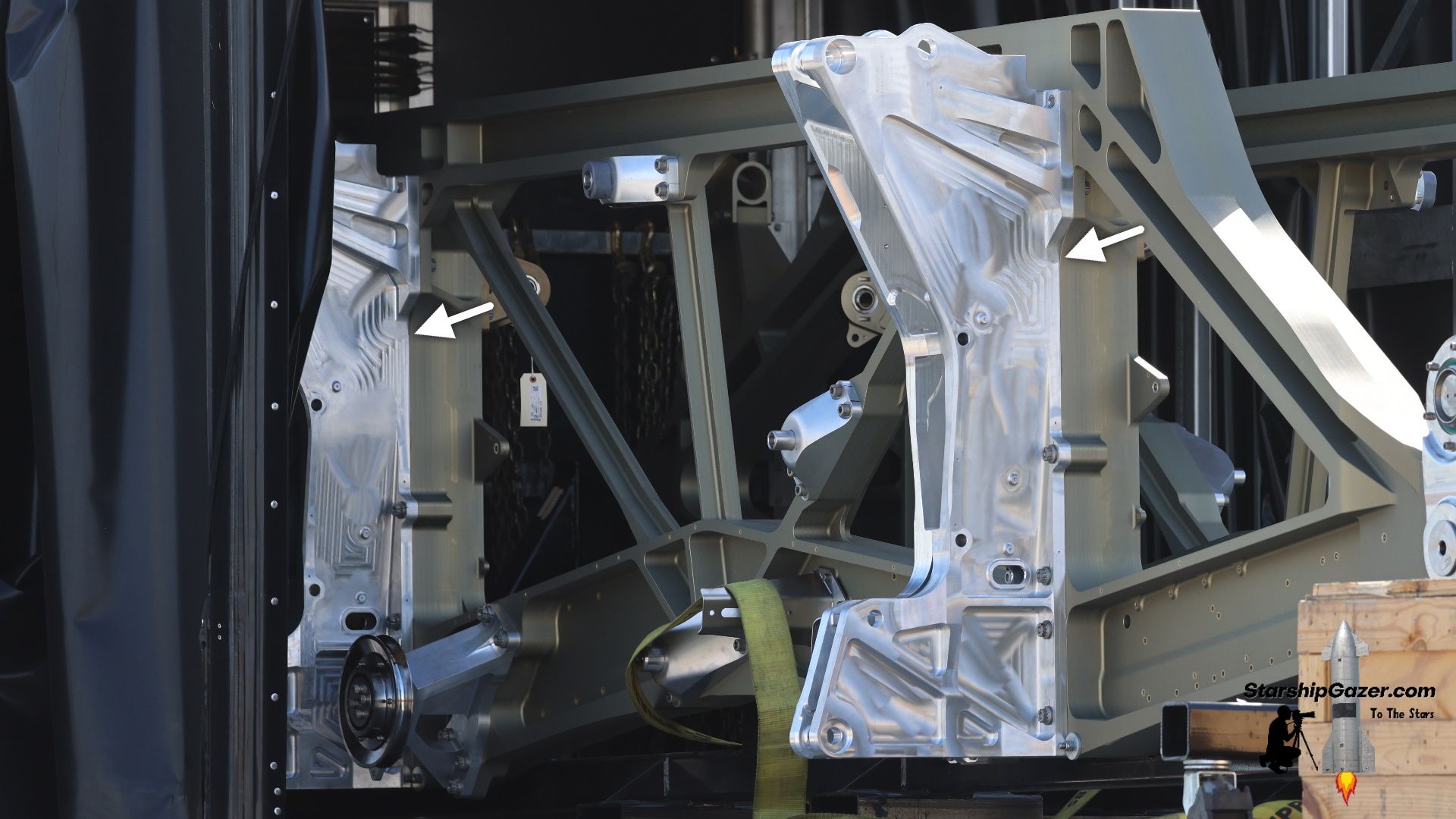
To begin, let's look at the two base pieces, upon which everything is mounted. These relatively thin and flat pieces of steel, indicated by arrows in the image below, had additional reinforcements added in some regions and served as a sturdy base for the dispenser.
Compared to this, the redesigned dispenser is... very different. In fact, the new approach is quite confusing at a glance.
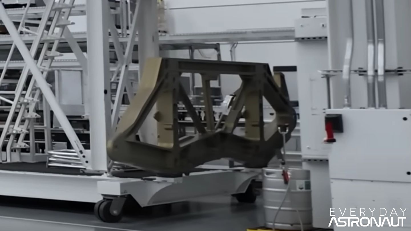
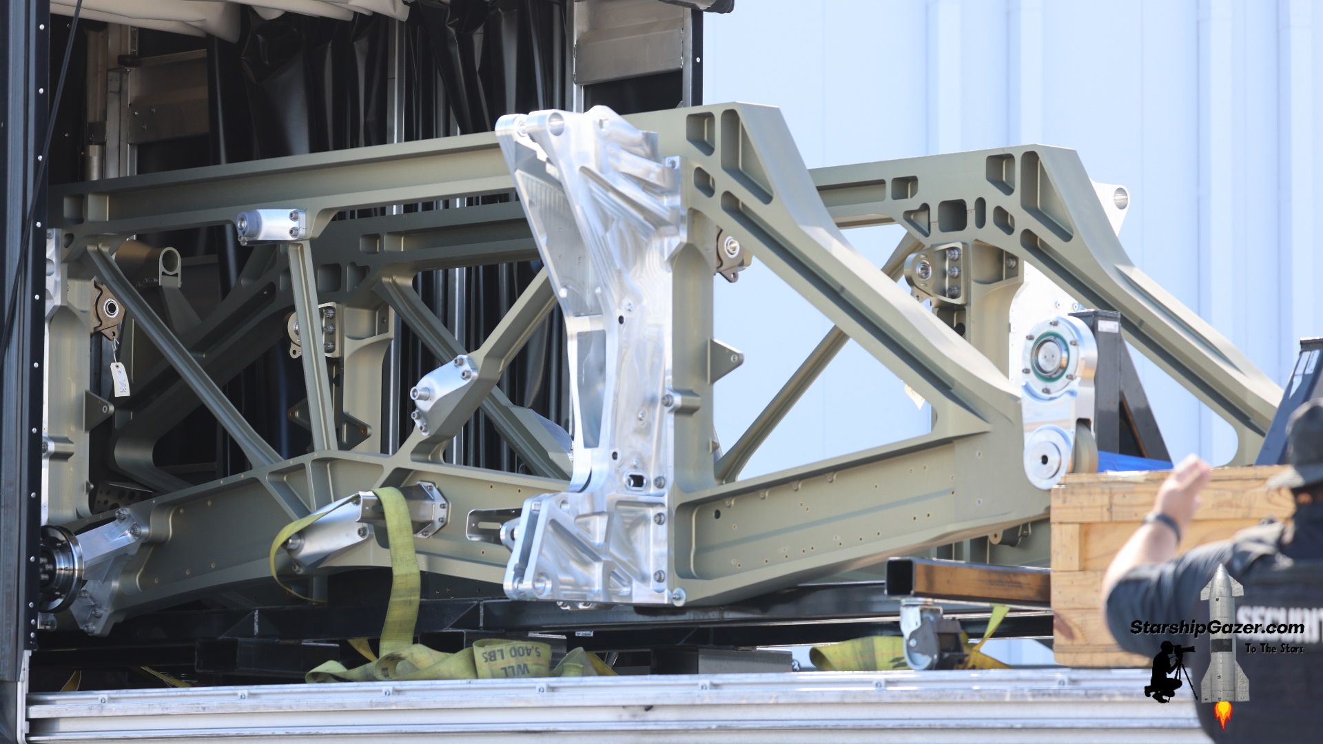
The redesigned base pieces are now very thick pieces of metal with a gold-ish tint. The new design also has a strange semi-angular shape that completely differs from the older rectangular base pieces.
There are still diagonal supports in the middle, but they certainly are not simple triangular cutouts. Additional pieces are bolted onto this frame component in the images below, but we are primarily focusing on the gold-ish piece.
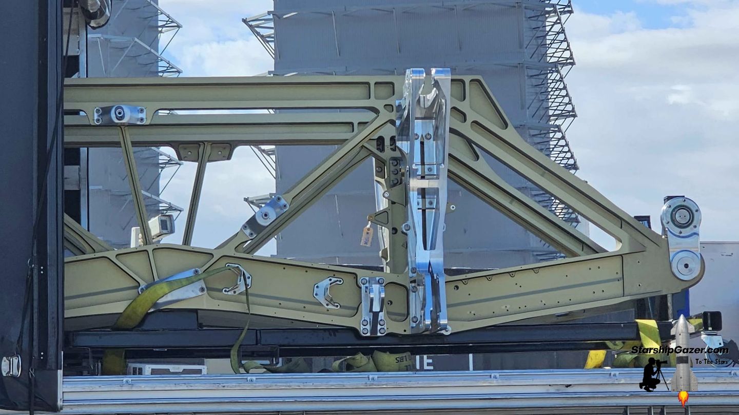
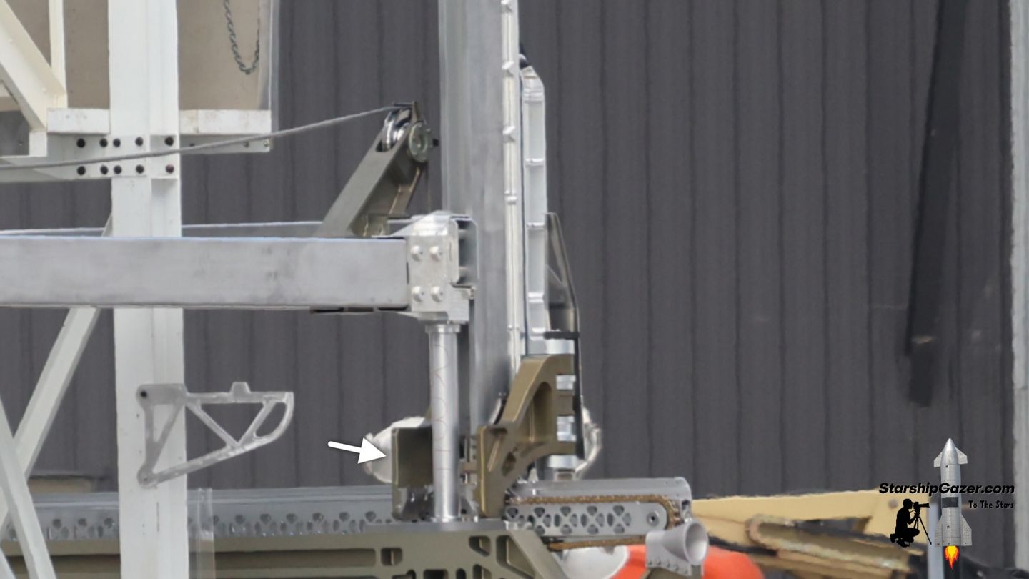
At the ends of each base piece, there are cylindrical connections for pins to insert into. These seem to serve as the mounting hardware for the PEZ dispenser, likely corresponding with a matching mount inside the payload bay.
A similar comparison can be made for the two horizontal supports at the base of the dispenser.
Previously, these were rectangular beams formed out of sheet metal with triangular perforations. There were four horizontal beams, two of which appeared to be structural, while the other two were housings for a cable and pulley system.
The latter two have been deleted entirely on the updated design.

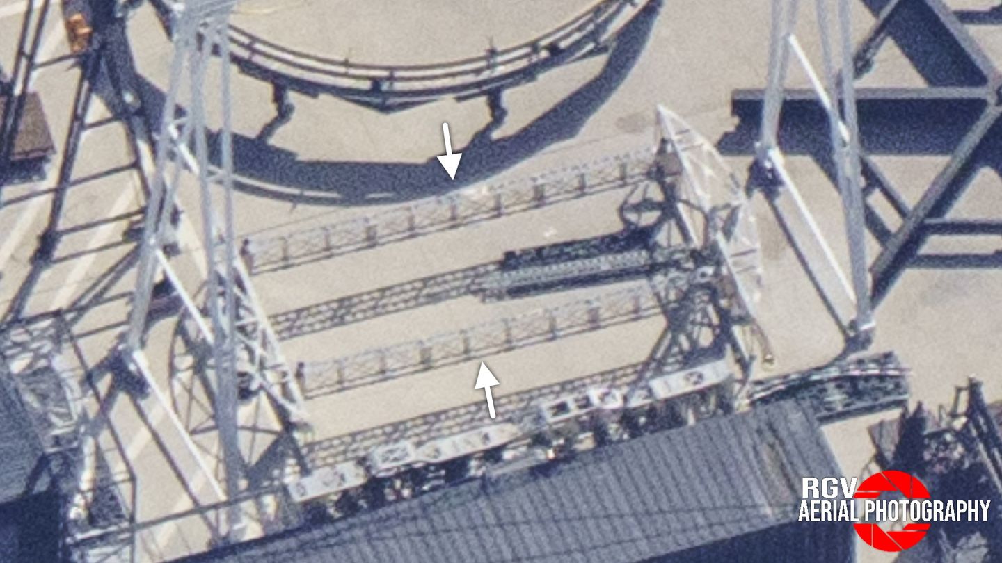
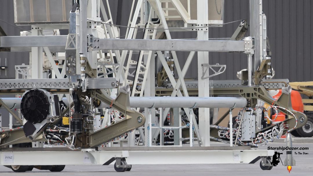
For the new design, the two horizontal supports have been replaced with giant tubes. These two hollow tubes connect the two base pieces together and finish off the "base structure" of the dispenser.
Once again, we can see that SpaceX is not using components formed out of sheet metal, which visually makes the design much simpler. They quite literally just put a pipe.
As for the mass of these components, we'll get to that.

Let's make one more comparison.
The satellite retention frame on the original dispenser was formed from several flat steel pieces with triangular cutouts, just like the old base pieces and horizontal beams. These were essentially shaped like I-beams.
Now, try to guess what this looks like on the new version.
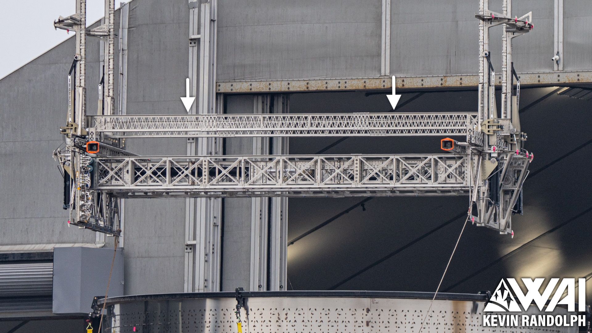
If you guessed that the frame now has solid faces, you have basic pattern recognition skills. Congratulations.
These are now rectangular tubes with solid faces, connected together with bolts. This once again means that the perforated steel components have been replaced with much larger components that have solid faces or a thicker construction.
The dry mass of a launch vehicle is very important, especially for a second stage. This dispenser is Starship's payload adapter, meaning that it will always remain with the ship through the ascent and descent phases of flight. So, wouldn't these changes make it heavier?
The following section is largely speculation.
One of the benefits of the new design is the removal of the tiny triangular perforations that would need to be cut out before assembly, so the fabrication process has been simplified in that respect. If SpaceX wants to mass-produce these ships, then some sacrifices for ease of production would be understandable.
However, by doing this, the dry mass of a steel component would be greatly increased, likely making this change irrational due to its potential impact on the vehicle's performance. Furthermore, the bulkiness and thickness of the new components would also likely be detrimental, as the new base pieces are several times thicker than the older ones in some areas. That is pretty insane.
Due to the new dispenser's... weird appearance, we began to formulate a theory. Since then, this theory seems quite likely and supports what we have been observing.
We suspect that the new dispenser may be entirely made out of aluminum, and not steel like the older design. Compared to a stainless steel structure, the mass of an aluminum frame would almost certainly yield a lower total mass, even considering the bulkier structure.
This would explain why the components forming the dispenser's structure are so much beefier compared to the original design. Maintaining the rigidity and strength of the dispenser, while potentially lowering the overall mass, would be a win for all parties involved.
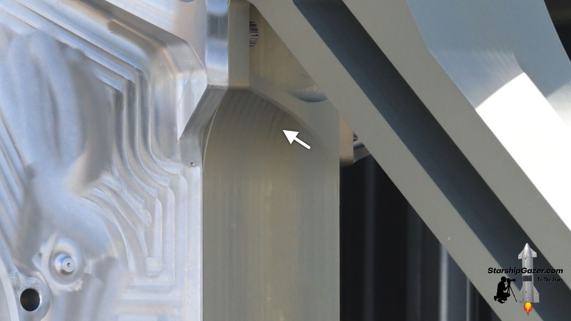
The large gold-ish base pieces for the new dispenser are almost certainly milled out of large blocks of metal, and we can even see the markings from this process. This probably isn't a cheap process due to the size of the base pieces. It seems very unlikely that SpaceX would machine each dispenser base out of a gigantic stainless steel block, and it would likely be very expensive.
We suspect that gold tint is likely gained during an anodization or treatment following machining.
Providing further weight to this theory, recall the cylindrical attachment points on each end of the base pieces that serve as the connections between the dispenser and the ship. If this base structure was aluminum, a connection using fasteners may be a much easier method of attaching it to the steel ship.
Why does the dispenser need to be made out of steel? Was it simply steel because the rest of the vehicle is made out of steel,? If so, then you may arbitrarily be missing out on an optimized and more efficient design. The dispenser doesn't experience the same extreme environment ship's exterior and it already doesn't match the rest of the ship's hardware, so differences should be expected.
While we cannot definitively say that SpaceX has changed the dispenser's material, it doesn't seem all that improbable. Sometimes it's fun to consider a handful of possibilities, even if they aren't backed by a whole lot. If anything, it's something to ponder as we continue.
Now, back to the comparisons.
Acting as guide rails for the Starlink satellites, there are columns situated on each corner of the dispenser. Each column was hollow and had an open face to allow small indexing components on the satellite to use the columns as a track.
The height of these columns is directly correlated with the number of satellites that the dispenser can hold. For this design, the dispenser could hold roughly 20 Starlinks in two stacks. As such, we believe the previous design could hold approximately 40 Starlinks.
Between each pair of columns, semicircular frame pieces would attach to the ship, ensuring that the dispenser's frame stayed rigid and straight. Two horizontal beams at the top would also assist in keeping the assembly rigid.
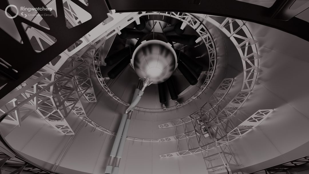
This rendering shows what the previous ship would have looked like with the older PEZ dispenser. Notice how the entirety of the nosecone volume is empty.
The columns on the new dispenser are similar to the old design, however, they now feature angled tops to presumably connect to the ship's nosecone.
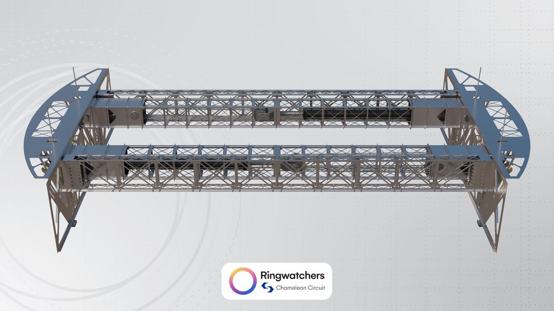
These columns are also noticeably taller, expanding the capacity of the dispenser. According to Chameleon Circuit's 3D recreation, we believe that the new dispenser can hold approximately 54 Starlink V3 satellites, which is about 14 more compared to before, or two stacks of seven.
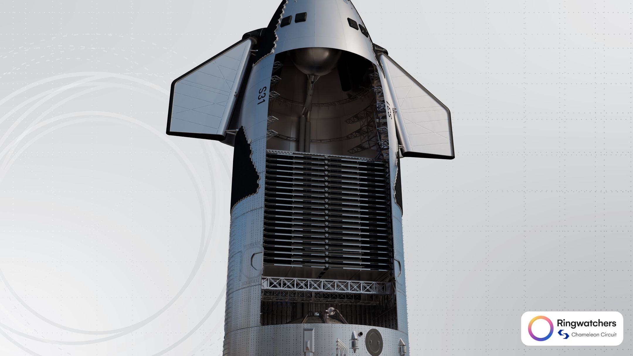
The taller dispenser, in combination with the shorter payload bay, results in the PEZ dispenser entering the nosecone volume. As previously discussed, the new ship utilizes the entirely of its payload volume and aims to delete dead spaces. The dispenser ends just below the methane header tank on the new design.
As such, we believe that the upgraded ship looks something like this when it is completely filled with Starlinks.
Unlike the previous design, you can see how the entire payload bay is filled to the top. It is undoubtedly more efficient.
Fascinatingly, an official rendering of the previous ship design deploying Starlink satellites from a couple of years ago also depicts 54 Starlink satellites in the payload bay. In our original PEZ dispenser article, we noted that this was an inaccuracy.
If this wasn't just coincidental, it seems that SpaceX has had this number in mind for quite some time.
With the capacity discussion aside, we can return to the dispenser's structure.
There are no semicircular frames or horizontal components connecting the columns on the new dispenser design, but now it's time to recall the horizontal frames inside the payload bay from earlier.
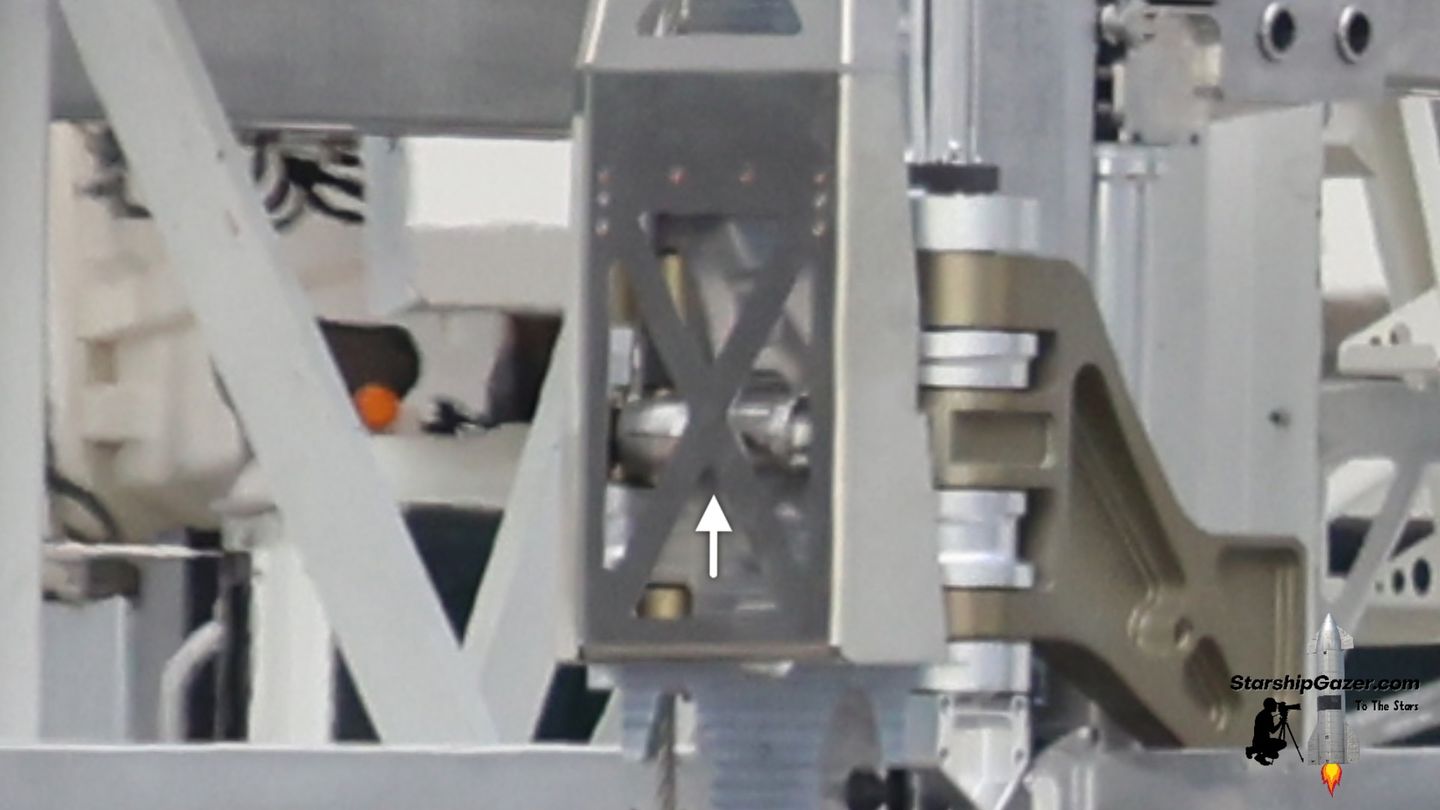
On both the columns and the base structure, there are four connections facing outward in each corner at varying heights. As such, there are 16 total connections on the left and right sides of the dispenser in addition to the four large ones at the bottom.
So, there are four different levels of connections on the dispenser. You may recall that there were four frames inside the payload bay, with three in the barrel and one in the nosecone.
In a 3D model, oh look, they match up perfectly.
We suspect that struts extend from these connections and secure the dispenser to the side of the ship. This likely simplifies the installation of the dispenser, as technicians do not need to attach each semicircular frame to the ship, but rather, can likely just pin the dispenser into place.
Rolling System
Since the Starlinks cannot be passively deployed like on the Falcon 9, the rolling system inside the PEZ dispenser propels the satellites out of the door. This system utilizes two parallel chain drives to roll the lower pair of satellites simultaneously.
There are always two stacks of Starlinks being lifted in tandem, which means there will always be two Starlinks deployed at the same time. As such, the chain drives must be long enough to reach both satellites on the bottom layer of the dispenser.
The old PEZ dispenser had two chain drives, with one on either side of the dispenser, and we can follow the path of the chain in the image below.
Since the black motor unit for the chain was situated on one of the PEZ dispenser's base pieces, the chain was forced to go down and loop back around.
The following render shows a stripped-down model of the old dispenser and the path that the chain took.
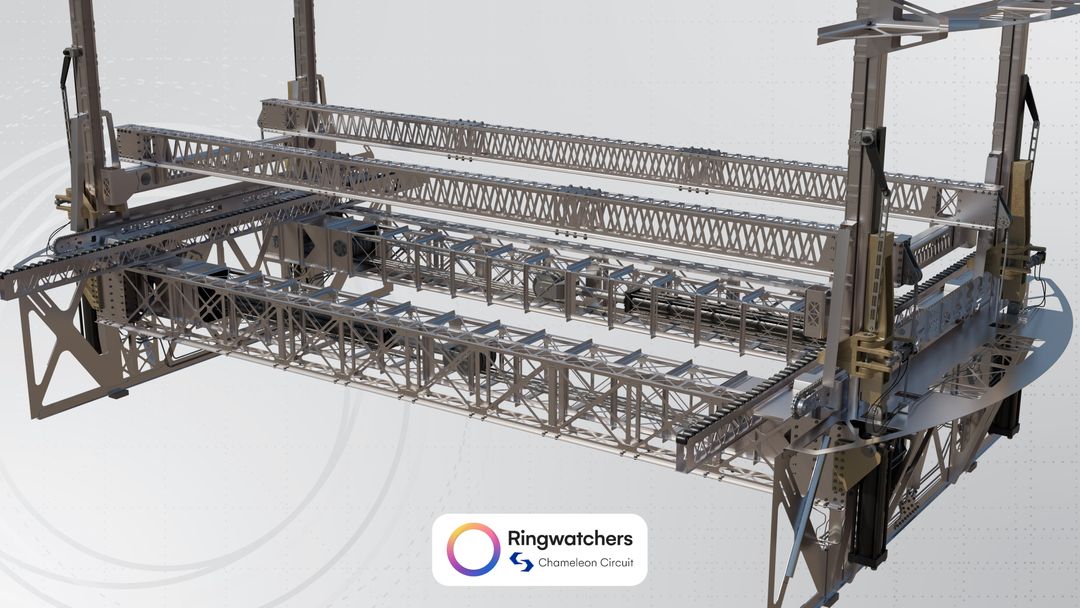
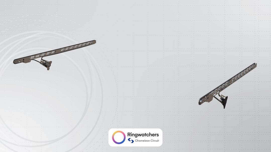
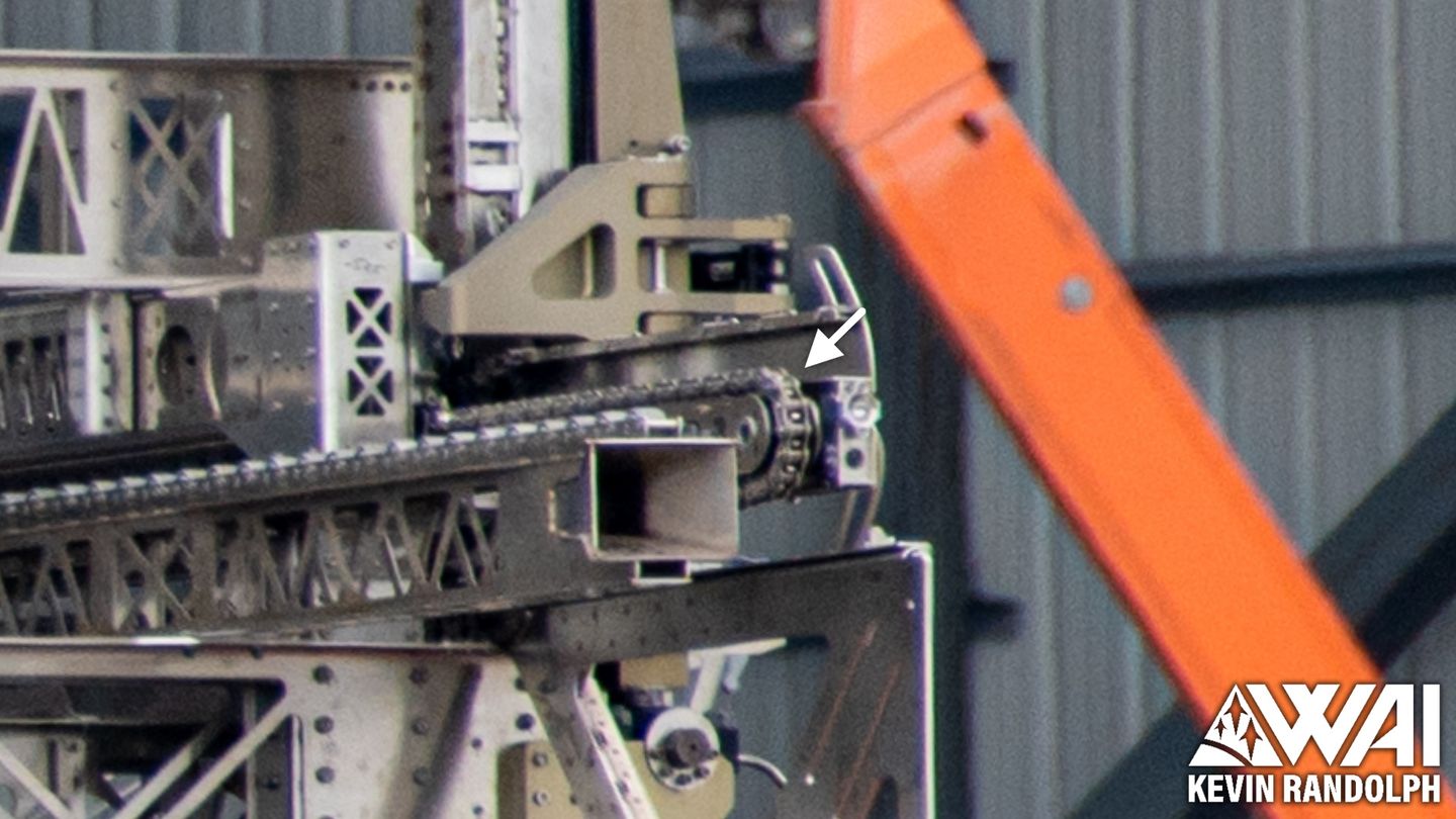
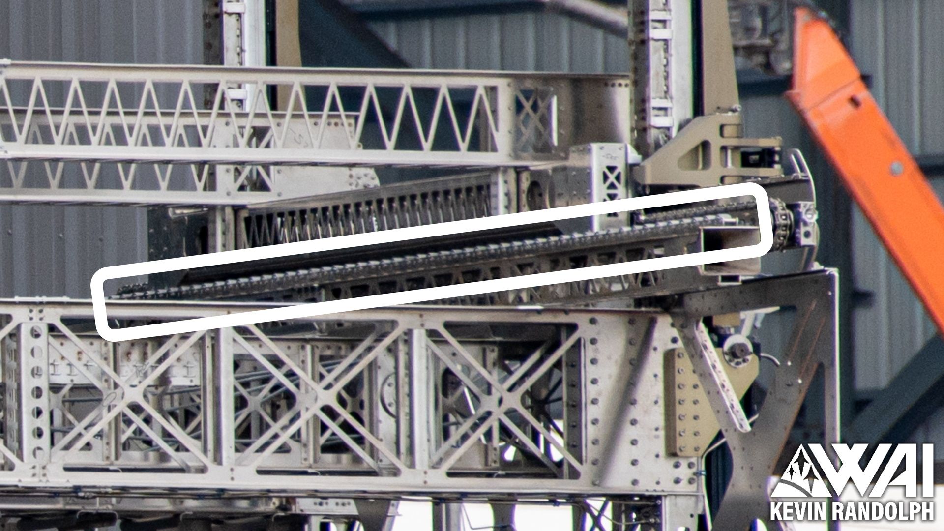
The new dispenser system is nearly identical, however, the chain's path is greatly simplified.
Rather than having an offset motor on one of the base pieces, it is now placed in line with the chain, and therefore the chain is just one continuous loop with no fancy bends. This is a relatively small change, but likely improves the ease of assembly and just removes an otherwise unnecessary complication in the design.
The previous design of the PEZ dispenser also had floating rollers that the Starlinks could sit on, helping guide them out. These weren't anything fancy and were quite simply just rollers.
We aren't sure if the new design has similar rollers, as they could be built into the large machined base pieces, but we don't have the imagery to confirm if they are present or not. Theoretically, the satellites may be able to just sit on the chain drives.
Lifting & Stacking System
In an ideal world, a lifting system inside the PEZ dispenser would not be necessary. However, in that ideal world, Starship can only carry two Starlinks. So, there's a lifting system.
The lifting system allows the dispenser to continually raise and lower Starlinks during the loading and deployment sequences using similar technologies to what is found in pallet stacking machines. For a loading sequence, it grabs the lowest set of satellites, raises them, stacks them on another pair, and then resets back to the bottom to repeat.
There are four lifting assemblies, with one located at the end of each satellite.
The old dispenser had an upward-facing hydraulic piston to serve as the "lifter". This piston did the heavy work, lifting the actual Starlink and the hardware that was holding the Starlink. We'll call that hardware the "clamping unit" for simplicity.
The clamping unit had a few components, the most obvious of which was the set of clamp arms that actually grabbed the satellite. Notice the notched ends that allowed them to slide beneath the satellite's lifting points.
A smaller hydraulic piston opened and closed these clamp arms, allowing the satellite to be released. Remember, all of this is attached to the upward-facing piston from earlier, and can therefore be moved up and down.

These clamp arms and their associated piston were attached to a component that could slide up and down the columns of the PEZ dispenser, taking the satellite with it. Essentially, you have a piston lifting a set of clamp arms up and down.
Below is an image of two complete "lifting assemblies". Remember, there were four total on the entire PEZ dispenser.
The new design is similar since it needs to do the same thing, but it has been redesigned a little bit.
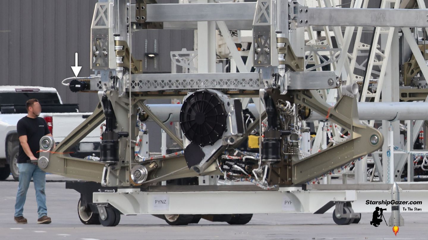
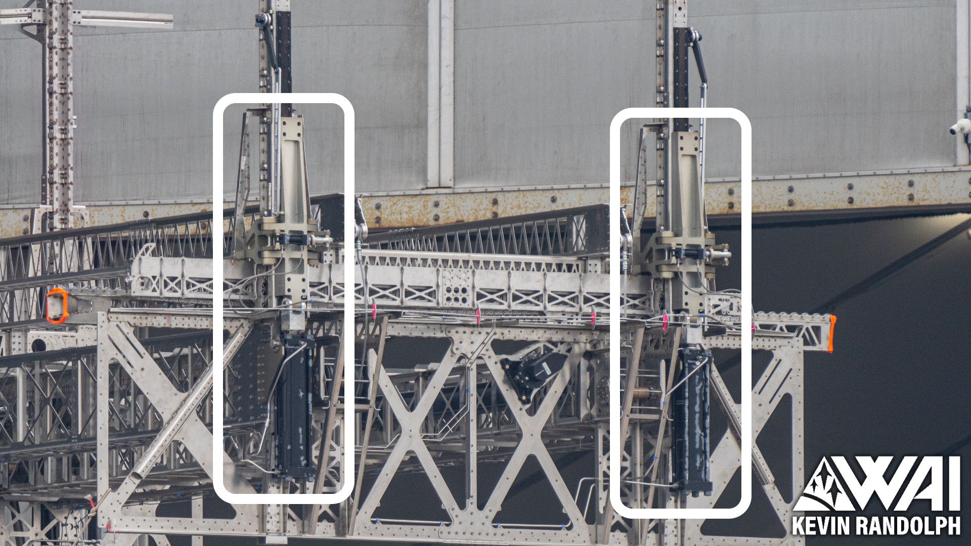
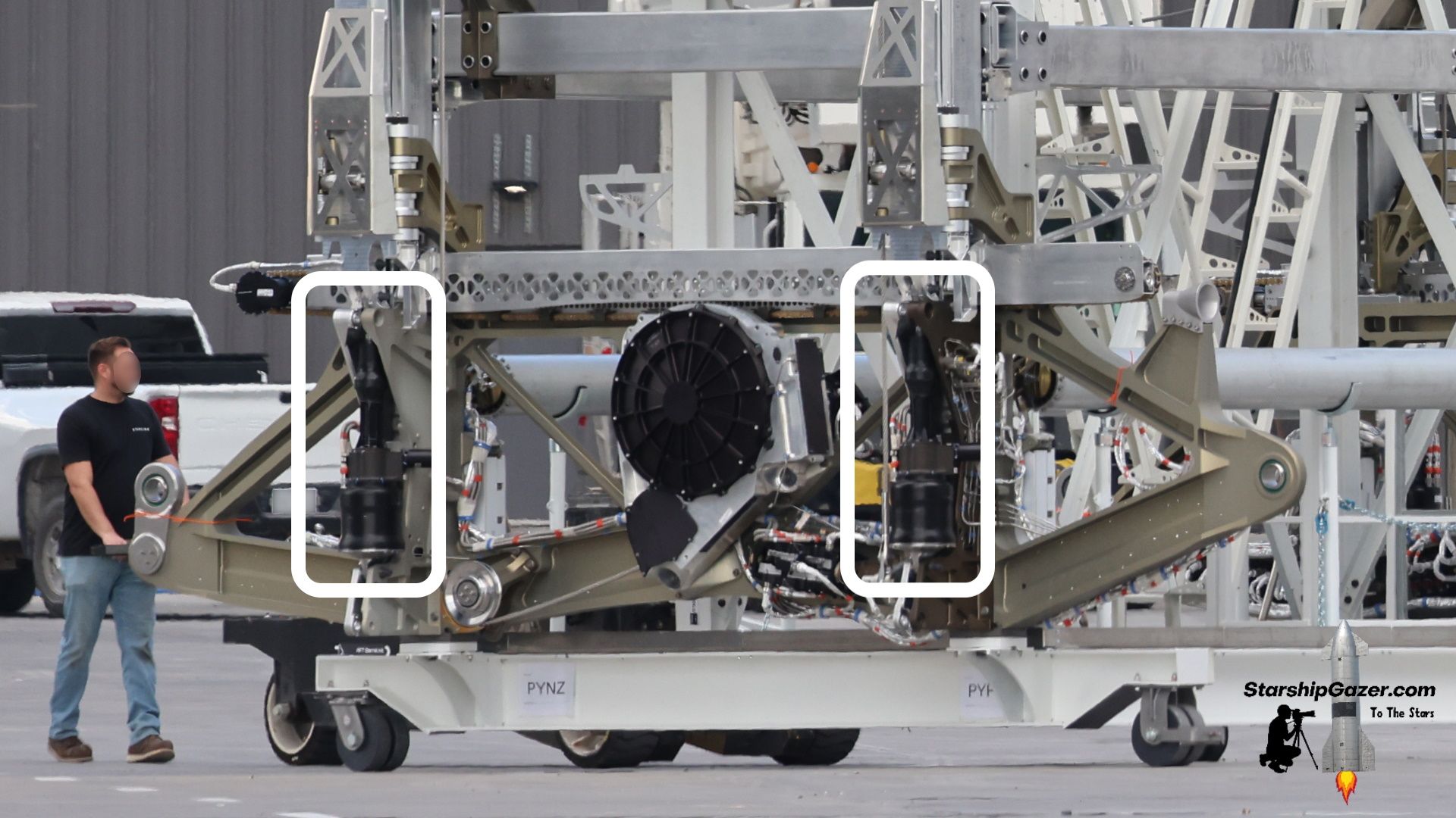
Starting off, there are once again four lifting assemblies, with one positioned at the end of each Starlink. Functionally, they work just the same as before and use the same principle as a pallet stacker.

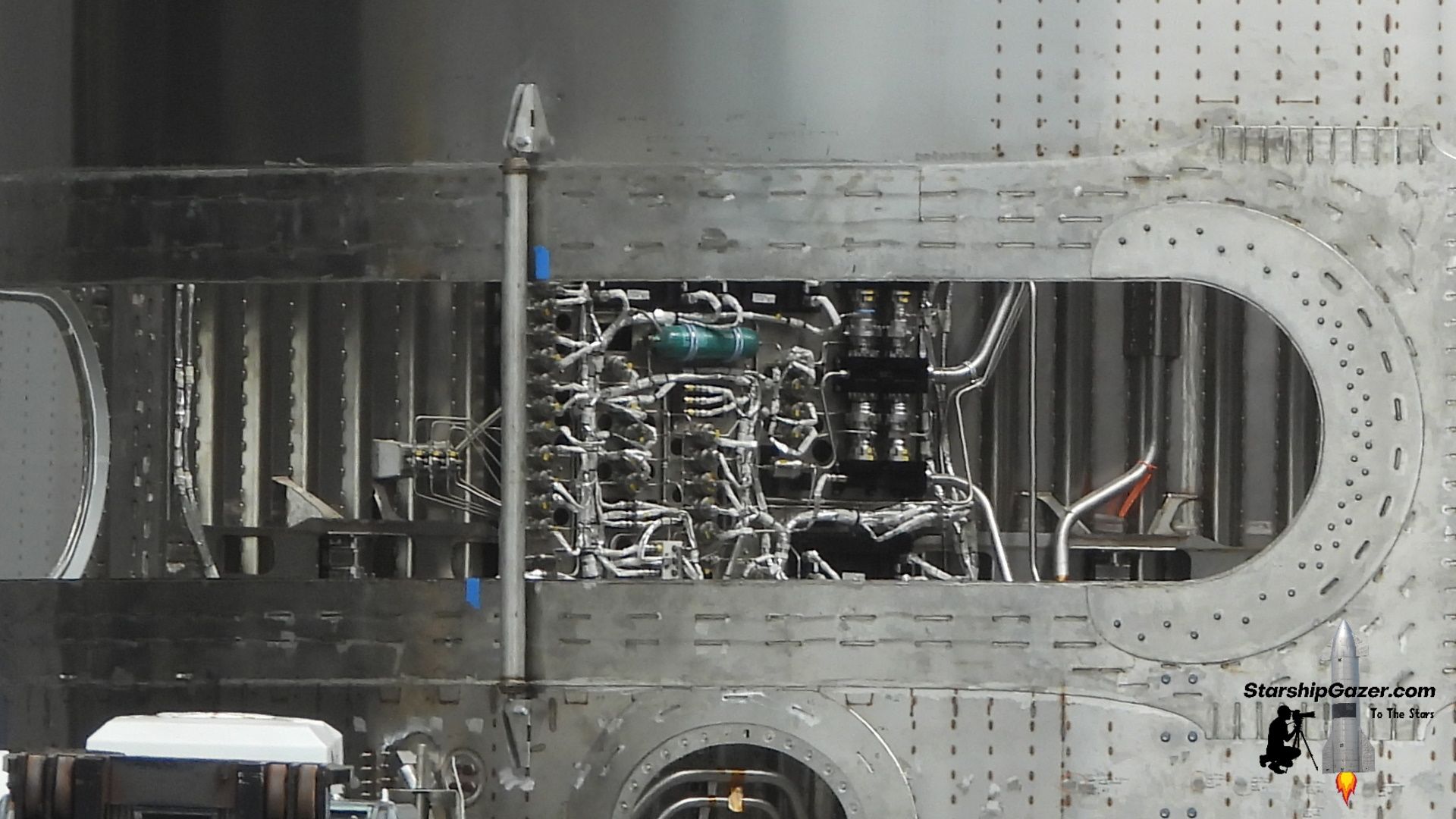
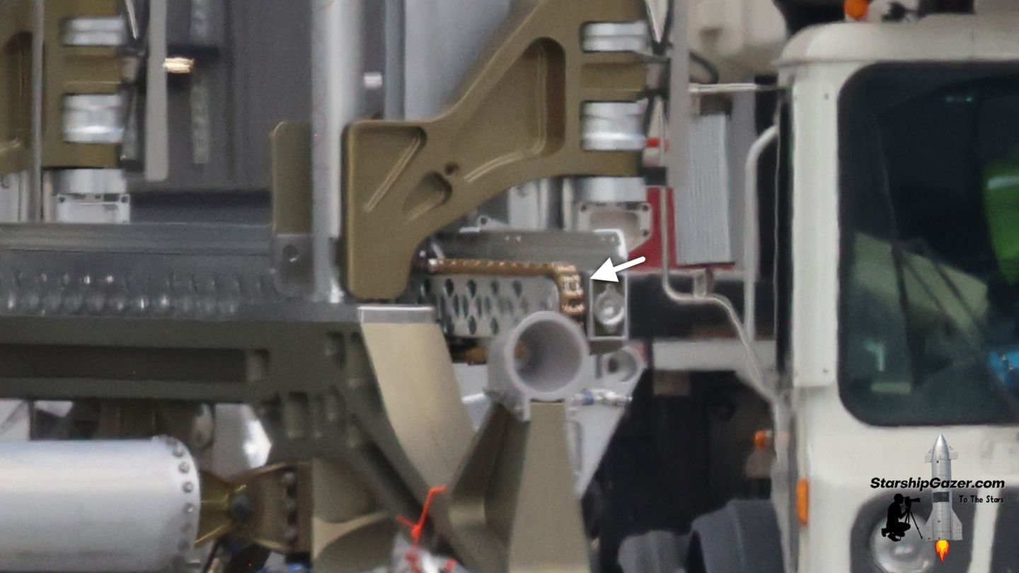
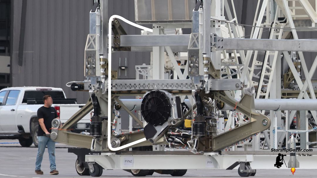
An upward-facing piston is mounted at the base of the dispenser, but this is visibly not the same component.
In fact, it looks quite similar to the electric thrust vector control arms utilized on the Raptor engines. While this piston is almost certainly not the same device, we believe that it is an electric actuator rather than a hydraulic one. The lack of hydraulic pipework is also a pretty good indicator.
This change comes as no surprise, as SpaceX has been adamantly removing all hydraulics from the Starship design, and these were some of the last major components to be changed over.
Clamping arms are once again attached to the upward-facing actuator, allowing the dispenser to grab the Starlinks.
The new clamp arms are shaped differently and are a bit larger compared to the older dispenser, but overall have the same notched ends that slot underneath the satellite's lifting points.
A small actuator is once again found behind these clamps to open and close them, although it is now found behind a metal shield. Once again, we suspect that this actuator is now electric instead of hydraulic.
Retention System
In a zero-g environment, the Starlink satellites will not naturally settle to the bottom of the PEZ dispenser, and without being settled to the bottom, the chain drives cannot propel them out of the door. To resolve this issue, a retainer system is built into the PEZ dispenser, which allows a cable system to pull down on the stack of satellites.
Of all the systems inside the old PEZ dispenser, this was arguably the most concerning one. The older dispenser featured a complex pulley and cable system to pull down on the retention frame, utilizing the mechanical advantage of the system and a large piston. At a glance, this system appeared to be needlessly complex and introduced several failure points where cables could slip or bind during ascent.
We're not going to get into how we figured this out, so we'll just look at the 3D renderings of what this older design looked like. You can see the numerous sheaves and blocks that this system was composed of. Also notice how it was mirrored, essentially doubling everything.

Now, let's take a look at the new design. Funny enough, this system is what we originally assumed was used on the old dispenser before actually analyzing how it functioned. Once again, the system is mirrored across the dispenser, so we will look at only one half for the sake of this explanation.
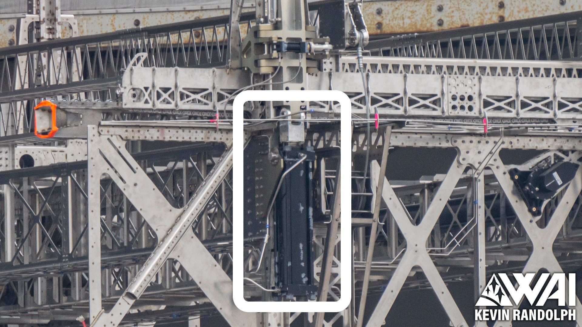
A massive electric winch is attached to the side of the PEZ dispenser, with a cable exiting it and connecting to the actual retainer. Instead of the previous design's continuously retracting piston, this drum should be able to collect the cable and slowly pull it down during the deployment sequence.

A cable exits this winch, travels across the base components, and makes its way up to the retention frame. This is where some noticeable differences in this system come into play.
The retention frame is a component that sits on top of the uppermost pair of Starlink satellites. When the system engages, it pulls the satellites to the bottom of the dispenser.
The white line in the image below follows the path of this cable and is situated adjacent to it.
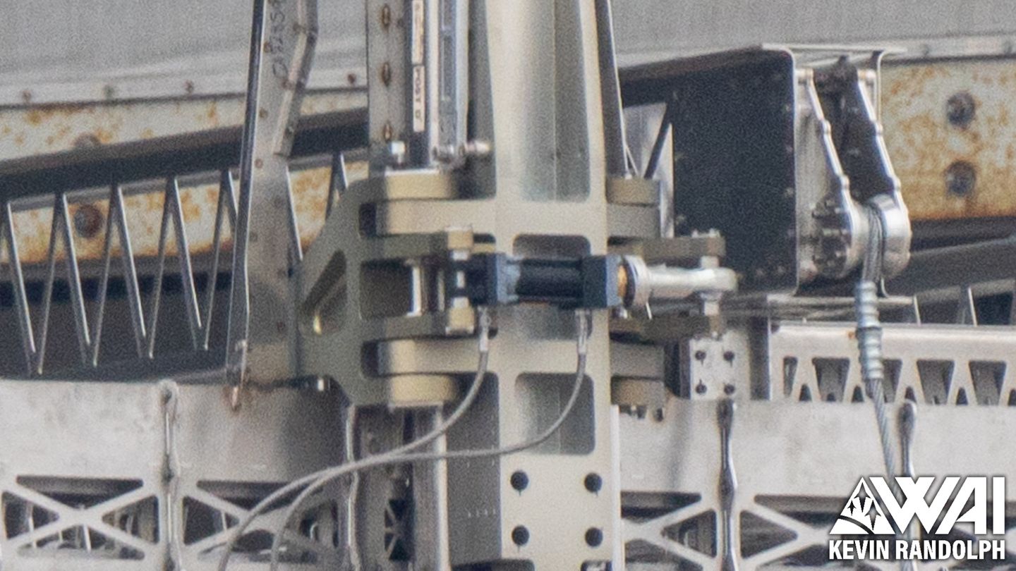
Instead of connecting to the retention frame, it actually wraps over and runs across the dispenser. From here, it runs down and we believe it connects to a fixed end.
In this image, we are looking at the opposing side's cable system.
When the winch begins to pull on the cable, the entire frame will be pulled down as a result. By having it mirrored on the other side, both edges of the retention frame are being pulled down, ensuring the satellites are pushed to the bottom of the dispenser evenly and safely.
To work properly with the new design, the retention frame now has raised corners for the cable to run across.
If there's one takeaway you should have, it's that the entire dispenser appears to use electric actuation systems instead of hydraulics.

And that is Starship's revised payload deployment system, which will hopefully see use for the first time in 2025 as SpaceX works to bring Starship online.
Customer payloads are still a whole other ballpark that SpaceX will need to deal with, but the PEZ dispenser system serves as a good solution for the SpaceX-specific payloads that these initial flights will primarily fly. We still need to see this upgraded version undergo flight testing before we can call it a solid design, but SpaceX has overcome much larger hurdles in this program already.
Next, we can move onto the final article in this series, as we discuss Starship's upgraded heat shield and some other miscellaneous items that we haven't yet discussed.