Shenzhen Growatt New Energy Co., Ltd. Shenzhen Growatt New Energy Co., Ltd.[古瑞瓦特新能源股份有限公司]
4-13/F, Building A, Sino-German (Europe) Industrial Park, Hangcheng Blvd, Bao’an District, Shenzhen, China 中国深圳市宝安区航城大道中德(欧洲)工业园 A 栋 4-13 楼
T +8675527471942
PV Hybrid Inverter 光伏混合逆变器
E service@ginverter.com
(SPE 12000 ES、SPE 10000 ES、SPE 8000 ES) (SPE 12000 ES、SPE 10000 ES、SPE 8000 ES)
W www.ginverter.com
User Manual 用户使用手册
Version: 1.3 (PN:044.SK0014903) 版本:1.3 (PN:044.SK0014903)
This manual is valid for the following devices: 本手册适用于以下设备:
SPE 12000 ES 单精度仪 12000 ES
SPE 10000 ES
SPE 8000 ES
1.2 Scope 1.2 范围
This manual describes the assembly, installation, operation and troubleshooting of this unit. Please read this manual carefully before installations and operations. 本手册描述了本机的组装、安装、作和故障排除。请在安装和作前仔细阅读本手册。
1.3 Target Group 1.3 目标群体
This document is intended for qualified persons and end users. Tasks that do not require any particular qualification can also be performed by end users. Qualified persons must have the following skills: 本文档适用于合格人员和最终用户。不需要任何特定资格的任务也可以由最终用户执行。合格人员必须具备以下技能:
Knowledge of how an inverter works and is operated. 了解逆变器的工作原理和作方式。
Training in how to deal with the dangers and risks associated with installing and using electrical devices and installations. 有关如何处理与安装和使用电气设备和装置相关的危险和风险的培训。
Training in the installation and commissioning of electrical devices and installations. 电气设备和装置的安装和调试培训。
Knowledge of the applicable standards and directives. 了解适用的标准和指令。
Knowledge of and compliance with this document and all safety information. 了解并遵守本文件和所有安全信息。
1.4 Safety Instructions 1.4 安全指导
/_\\triangle WARNING: This chapter contains important safety and operating instructions. Read and keep this manual for future reference. /_\\triangle 警告: 本章包含重要的安全和作说明。阅读并保留本手册以备将来参考。
Before using the unit, read all instructions and cautionary marking on the unit, the batteries and all appropriate sections of this manual. The company has the right not to quality assurance, if not according to the instructions of this manual for installation and cause equipment damage. 在使用本机之前,请阅读本机、电池和本手册所有适当部分上的所有说明和警告标记。本公司有权不予质量保证,如不按本说明书的指示进行安装而造成设备损坏。
All the operation and connection please professional electrical or mechanical engineer. 所有作和连接请专业的电气或机械工程师。
All the electrical installation must comply with the local electrical safety standards. 所有电气安装必须符合当地电气安全标准。
When install PV modules in the daytime, installer should cover the PV modules by opaque materials, otherwise it will be dangerous as high terminal voltage of modules in the sunshine. 白天安装光伏组件时,安装人员应使用不透明材料覆盖光伏组件,否则在阳光下组件端电压高会很危险。
CAUTION-To reduce risk of injury, charge only deep-cycle lead-acid type rechargeable batteries and lithium batteries. Other types of batteries may burst, causing personal injury and damage. 注意 - 为降低受伤风险,请仅为深循环铅酸型充电电池和锂电池充电。其他类型的电池可能会爆裂,从而导致人身伤害和损坏。
Please be clear which kind of battery system you want, lithium battery system or lead-acid battery system, if you choose the wrong system, energy storage system can’t work normally. 请明确您想要哪种电池系统,锂电池系统还是铅酸电池系统,如果选错系统,储能系统无法正常工作。
NEVER charge a frozen battery. 切勿为冻结的电池充电。
Be very cautious when working with metal tools on or around batteries. A potential risk exists to drop a tool to spark or short circuit batteries or other electrical parts and could cause an explosion. 在电池上或周围使用金属工具时要非常小心。存在掉落工具以产生火花或使电池或其他电气部件短路的潜在风险,并可能导致爆炸。
For optimum operation of this inverter, please follow required spec to select appropriate cable size. It’s very important to correctly operate this inverter. 为了此逆变器的最佳运行,请按照要求的规格选择合适的电缆尺寸。正确作此逆变器非常重要。
Please strictly follow installation procedure when you want to disconnect AC or DC terminals. Please refer to INSTALLATION section of this manual for the details. 当您想断开 AC 或 DC 端子时,请严格按照安装程序进行作。有关详细信息,请参阅本手册的 INSTALLATION 部分。
GROUNDING INSTRUCTIONS -This inverter should be connected to a permanent grounded wiring system. Be sure to comply with local requirements and regulation to install this inverter. 接地说明 - 此逆变器应连接到永久接地布线系统。请务必遵守当地要求和法规才能安装此逆变器。
NEVER cause AC output and DC input short circuited. Do NOT connect to the mains when DC input short circuits. 切勿导致交流输出和直流输入短路。当直流输入短路时,请勿连接到电源。
Make sure the inverter is completely assembled, before the operation. 作前确保逆变器已完全组装好。
Do not disassemble the unit. Take it to a qualified service center when service or repair is required. Incorrect re-assembly may result in a risk of electric shock or fire. 请勿拆卸设备。当需要服务或维修时,请将其带到合格的服务中心。不正确的重新组装可能会导致触电或火灾的危险。
To reduce risk of electric shock, disconnect all wirings before attempting any maintenance or cleaning. Turning off the unit will not reduce this risk. 为降低触电风险,请在尝试任何维护或清洁之前断开所有接线。关闭设备不会降低这种风险。
This is a class A product. In a domestic environment this product may cause radio interference in which case the user may be required to take adequate measures. 这是 A 类产品。在家庭环境中,本产品可能会造成无线电干扰,在这种情况下,用户可能需要采取适当的措施。
2. Product Overview 2. 产品概述
This is a multifunctional PV Hybrid inverter, integrated with a MPPT solar charge controller, a high frequency pure sine wave inverter and a UPS function module in one machine, which is perfect for off grid backup power and self-consumption applications. This inverter can work with or without batteries. 这是一款多功能光伏混合逆变器,集 MPPT 太阳能充电控制器、高频纯正弦波逆变器和 UPS 功能模块于一体,非常适合离网备用电源和自用应用。该逆变器可以在有电池或没有电池的情况下工作。
The whole system also need other devices to achieve complete running such as PV modules, generator, or utility grid. Please consult with your system integrator for other possible system architectures depending on your requirements. The WIFI / 4G module is a plug-and-play monitoring device to be installed on the inverter. With this device, users can monitor the status of the PV system from the mobile phone or from the website anytime anywhere. 整个系统还需要其他设备来实现完整运行,例如光伏组件、发电机或公用电网。请根据您的要求,咨询您的系统集成商,了解其他可能的系统架构。WIFI / 4G 模块是安装在逆变器上的即插即用监控设备。有了这个设备,用户可以随时随地通过手机或网站监控光伏系统的状态。
2.1 Product Features 2.1 产品特点
Rated power 8 KW to 12 KW , power factor 1. 额定功率 8 KW 至 12 KW,功率因数 1。
2 strings of MPPT, Max. PV array power 10000watt to 15000watt. 2 串 MPPT,最大光伏阵列功率 10000 瓦至 15000 瓦。
MPPT Voltage range 60Vdc-480Vdc60 \mathrm{Vdc}-480 \mathrm{Vdc}, 550 Voc . MPPT 电压范围 60Vdc-480Vdc60 \mathrm{Vdc}-480 \mathrm{Vdc} , 550 Voc .
Pure sine wave inverter and MPPT solar charge controller integrated inside. 内部集成纯正弦波逆变器和 MPPT 太阳能充电控制器。
Built-in ATS for automatic grid and generator switching. 内置 ATS,用于自动电网和发电机切换。
Able to work with or without battery. 能够在有电池或没有电池的情况下工作。
With CAN/RS485 for BMS communication. 带有 CAN/RS485 用于 BMS 通信。
WIFI/4G wireless monitoring(optional). WIFI / 4G 无线监控(可选)。
Parallel operation up to 9 unit(only with battery connected). 最多可并联运行 9 个单元(仅在连接电池的情况下)。
With grid tied function. 具有并网功能。
With dual outputs. 具有双输出。
With grid peak shaving. 带网格调峰。
With external CT for zero exporting into grid. 带外部 CT 用于零点导出到网格中。
2.2 Panel and Port Definitions 2.2 面板和端口定义
Panel operation 面板作
1. LCD display 1. LCD 显示屏
2. Status indicator 2. 状态指示灯
3. Charging indicator 3. 充电指示灯
4. Fault indicator 4. 故障指示灯
5. Function buttons 5. 功能按钮
Communication port 通讯端口
6. USB communication port 6. USB 通讯端口
19. WiFi / 4G communication port 19. WiFi / 4G 通讯端口
8. BMS communication port (support CAN/RS485 ) 8. BMS 通讯端口(支持 CAN/RS485)
9. RS485 communication port (for expansion) 9. RS485 通讯端口(用于扩展)
10. Parallel communication ports 10. 并行通信端口
11.DIP
Connection port 连接端口
14. Generator input 14. 发电机输入
15. Grid input 15. 网格输入
16.PE
17. AC output(main) 17. 交流输出(主)
18. AC output(smart load) 18. 交流输出(智能负载)
20. Battery input 20. 电池输入
22. PV1 input 22. PV1 输入
23. PV2 input 23. PV2 输入
Other 其他
12. EXT CT 12. 外部 CT
13. Dry contact 13. 干接点
21. Power on/off switch 21. 电源开/关开关
Panel operation
1. LCD display 2. Status indicator
3. Charging indicator 4. Fault indicator
5. Function buttons
Communication port
6. USB communication port 19. WiFi / 4G communication port
8. BMS communication port (support CAN/RS485 ) 9. RS485 communication port (for expansion)
10. Parallel communication ports 11.DIP
Connection port
14. Generator input 15. Grid input
16.PE 17. AC output(main)
18. AC output(smart load) 20. Battery input
22. PV1 input 23. PV2 input
Other
12. EXT CT 13. Dry contact
21. Power on/off switch | Panel operation | |
| :--- | :--- |
| 1. LCD display | 2. Status indicator |
| 3. Charging indicator | 4. Fault indicator |
| 5. Function buttons | |
| Communication port | |
| 6. USB communication port | 19. WiFi / 4G communication port |
| 8. BMS communication port (support CAN/RS485 ) | 9. RS485 communication port (for expansion) |
| 10. Parallel communication ports | 11.DIP |
| Connection port | |
| 14. Generator input | 15. Grid input |
| 16.PE | 17. AC output(main) |
| 18. AC output(smart load) | 20. Battery input |
| 22. PV1 input | 23. PV2 input |
| Other | |
| 12. EXT CT | 13. Dry contact |
| 21. Power on/off switch | |
3. Installation Instructions 3. 安装说明
3.1 Accessory list 3.1 配件清单
Before installation, please inspect the unit. Be sure that nothing inside the package is damaged. You should have received the following items in the package: 安装前,请检查设备。确保包装内没有损坏任何东西。您应该已在包裹中收到以下物品:
Part List 零件清单
A B C ◻\square
E
◻\square
Item 项目
Item Name 项目名称
Qty 数量
A
The unit 单位
1
B
Communication cable 通讯电缆
1
C
Parallel communication cable 并联通信电缆
1
D
R-type terminal R 型端子
1
E
O-type terminal O 型端子
4
F
User manual 用户使用手册
1
Part List A B C◻ E ◻
Item Item Name Qty
A The unit 1
B Communication cable 1
C Parallel communication cable 1
D R-type terminal 1
E O-type terminal 4
F User manual 1 | Part List | | | A B C$\square$ | | | | E | $\square$ |
| :--- | :--- | :--- | :--- | :--- | :--- | :--- | :--- | :--- |
| Item | Item Name | Qty | | | | | | |
| A | The unit | 1 | | | | | | |
| B | Communication cable | 1 | | | | | | |
| C | Parallel communication cable | 1 | | | | | | |
| D | R-type terminal | 1 | | | | | | |
| E | O-type terminal | 4 | | | | | | |
| F | User manual | 1 | | | | | | |
3.2 Points for attention 3.2 注意事项
Consider the following points before selecting where to install: 在选择安装位置之前,请考虑以下几点:
Install this inverter at eye level in order to allow the LCD display to be read at all times. 将此逆变器安装在与眼睛齐平的位置,以便始终读取 LCD 显示屏。
The ambient temperature should be between -10^(@)C-10^{\circ} \mathrm{C} and 50^(@)C50^{\circ} \mathrm{C} to ensure optimal operation. 环境温度应介于 和 50^(@)C50^{\circ} \mathrm{C} 之间 -10^(@)C-10^{\circ} \mathrm{C} ,以确保最佳运行。
The recommended installation position is to be adhered to the wall vertically. 推荐的安装位置是垂直粘附在墙上。
Do not install in too narrow confined space and pay attention to ventilation. 请勿安装在太狭窄的密闭空间内,注意通风。
Be sure to keep other objects and surfaces as shown in the right diagram to guarantee sufficient heat dissipation and to have enough space for removing wires. 请务必保留右图所示的其他物体和表面,以保证足够的散热并有足够的空间来移除电线。
If the energy storage is installed in areas with salt damage, it will be corroded and may cause fire. Therefore, do not install it outdoors in areas with salt damage. The areas with salt damage are defined as the areas which are not 500 m away from shore or will be affected by sea breezes. The areas affected by the sea breezes vary depending on meteorological conditions (e.g. typhoons, monsoons) or topographical conditions (dams, hills). 如果储能安装在盐害区域,它会被腐蚀并可能引起火灾。因此,请勿将其安装在室外盐渍区域。盐害区域定义为距离海岸不到 500 m 或将受到海风影响的区域。受海风影响的区域因气象条件(例如台风、季风)或地形条件(水坝、丘陵)而异。 uarr\uparrow
SUITABLE FOR MOUNTING ON CONCRETE OR OTHER NON-COMMBUSTIBLE SURFACE ONLY. 仅适用于安装在混凝土或其他不可燃表面上。
Install the unit by screwing three screws. It’s recommended to use M4 or M5 screws. 拧上三个螺丝来安装设备。建议使用 M4 或 M5 螺丝。
Preparation for wiring. 布线准备。
Before connecting all wiring, please take off bottom cover by removing four screws as shown below. 在连接所有接线之前,请按照下图卸下 4 个螺钉,取下底盖。
3.3 Battery Connection 3.3 电池连接
! WARNING! !警告!
All wiring must be performed by a qualified person. 所有接线必须由合格人员进行。
Shock Hazard: Installation must be performed with care due to high battery voltage in series. 电击危险: 由于串联电池电压高,安装必须小心。
Always disconnect all circuit breakers before making connections to the battery power cable 在连接到电池电源线之前,请务必断开所有断路器
Make sure the battery power cable positive 确保电池电源线正极
must be connected to battery negative (-) 必须连接到电池负极 (-)
Do not place anything between the flat part of the inverter terminal and the ring terminal. Otherwise, a 请勿在逆变器端子的扁平部分和环形端子之间放置任何物品。否则,一个
short circuit may occur, 可能会发生短路,
Do not apply anti-oxidant substance on the terminals before terminals are connected tightly. 在端子连接紧密之前,请勿在端子上涂抹抗氧化物质。
3.3.1 Wiring preparation 3.3.1 布线准备
For safety operation and regulation compliance, it’s requested to install a separate DC breaker (over-current protector) or disconnect device between battery and inverter. It may not be requested to have a disconnect device in some applications, however, it’s still requested to have DC breaker installed. Please refer to typical amperage in below table as required breaker size. 为了安全作和法规遵从性,要求在电池和逆变器之间安装单独的直流断路器(过流保护器)或断开装置。在某些应用程序中,可能不会要求具有断开设备,但是,仍要求安装 DC 断路器。请参考下表中的典型安培数作为所需的断路器尺寸。
Recommended DC breaker specification of battery for a single inverter: 单个逆变器电池的推荐直流断路器规格:
Model 型
1 unit* 1 个单位*
SPE 12000 ES 单精度仪 12000 ES
400A//60VDC400 \mathrm{~A} / 60 \mathrm{VDC}
SPE 10000 ES
350A//60VDC350 \mathrm{~A} / 60 \mathrm{VDC}
SPE 8000 ES
300A//60VDC300 \mathrm{~A} / 60 \mathrm{VDC}
Model 1 unit*
SPE 12000 ES 400A//60VDC
SPE 10000 ES 350A//60VDC
SPE 8000 ES 300A//60VDC| Model | 1 unit* |
| :--- | :---: |
| SPE 12000 ES | $400 \mathrm{~A} / 60 \mathrm{VDC}$ |
| SPE 10000 ES | $350 \mathrm{~A} / 60 \mathrm{VDC}$ |
| SPE 8000 ES | $300 \mathrm{~A} / 60 \mathrm{VDC}$ |
2、It’s very important for system safety and efficient operation to use appropriate cable for battery connection. 2、使用合适的电缆连接电池对于系统安全和高效运行非常重要。
To reduce risk of injury, please use the proper recommended cable and terminal size as below. Recommended battery cable and terminal size: 为降低受伤风险,请使用适当推荐的电缆和端子尺寸,如下所示。推荐电池电缆和端子尺寸:
Model 型
Wire Size 线径
Torque value 扭矩值
SPE 12000 ES 单精度仪 12000 ES
2**22 * 2 AWG 2**22 * 2 美国线规
2**33.62mm^(2)2 * 33.62 \mathrm{~mm}^{2}
2-3Nm2-3 \mathrm{Nm}
SPE 10000 ES
2**22 * 2 AWG 2**22 * 2 美国线规
2**33.62mm^(2)2 * 33.62 \mathrm{~mm}^{2}
2-3Nm2-3 \mathrm{Nm}
SPE 8000 ES
2**32 * 3 AWG 2**32 * 3 美国线规
2**26.67mm^(2)2 * 26.67 \mathrm{~mm}^{2}
2-3Nm2-3 \mathrm{Nm}
Model Wire Size Torque value
SPE 12000 ES 2**2 AWG 2**33.62mm^(2) 2-3Nm
SPE 10000 ES 2**2 AWG 2**33.62mm^(2) 2-3Nm
SPE 8000 ES 2**3 AWG 2**26.67mm^(2) 2-3Nm| Model | Wire Size | | Torque value |
| :--- | :---: | :---: | :---: |
| SPE 12000 ES | $2 * 2$ AWG | $2 * 33.62 \mathrm{~mm}^{2}$ | $2-3 \mathrm{Nm}$ |
| SPE 10000 ES | $2 * 2$ AWG | $2 * 33.62 \mathrm{~mm}^{2}$ | $2-3 \mathrm{Nm}$ |
| SPE 8000 ES | $2 * 3$ AWG | $2 * 26.67 \mathrm{~mm}^{2}$ | $2-3 \mathrm{Nm}$ |
3、Battery Module Selection: Choose the appropriate battery according to the actual situation. 3、电池模块选择:根据实际情况选择合适的电池。
3.3.2 Battery power cable connection 3.3.2 电池电源线连接
Please follow below steps to implement battery connection: 请按照以下步骤实现电池连接:
Assemble battery ring terminal based on recommended battery cable and terminal size. 根据推荐的电池电缆和端子尺寸组装电池环端子。
Connect all battery packs as units requires. 根据需要连接所有电池组。
Insert the ring terminal of battery cable flatly into battery connector of inverter and make sure the bolts are tightened with torque of 2 Nm . Make sure polarity at both the battery and the inverter/charge is correctly connected and ring terminals are tightly screwed to the battery terminals. 将电池电缆的环形端子平直插入逆变器的电池连接器,并确保螺栓以 2 Nm 的扭矩拧紧。确保电池和逆变器/充电器的极性正确连接,并且环形端子已拧紧到电池端子上。
3.3.3 Lithium battery communication cable connection 3.3.3 锂电池通讯电缆连接
If used with lithium batteries, make sure to connect the BMS communication cable between the battery and the inverter. It is recommended to use lithium batteries that have been tested with our configuration. 如果与锂电池一起使用,请确保在电池和逆变器之间连接 BMS 通讯线。建议使用经过我们配置测试的锂电池。
Please follow below steps to implement BMS communication cable connection: 请按照以下步骤实现 BMS 通信电缆连接:
Connect one end of the battery’s communication cable to the inverter’s BMS communication port (below left), which supports RS485 or CAN protocols. 将电池通讯线的一端连接到逆变器的 BMS 通讯端口(左下方),支持 RS485 或 CAN 协议。
The other end of the battery communication cable plugs into the battery communication port (RS485 or CAN). 电池通信电缆的另一端插入电池通信端口(RS485 或 CAN)。
The inverter BMS port pin and RS485 port pin assignment shown as below: 逆变器 BMS 端口引脚和 RS485 端口引脚分配如下图所示:
Note: The RS485 port (for expansion) is used for communication expansion and connection to external devices. Note: In order to ensure the normal communication of lithium battery BMS, please set the battery type as “Li” in program 5, and then LCD will automatically switch to program 36 to select the communication protocol. You can Choose RS485 communication protocol which is from L01 to L50, and you can also choose CAN Communication protocol which is from L51 to L99. (About the specific protocol address of the inverter, please consult the dealer or manufacturer to choose which communication protocol to match the BMS). 请注意: RS485 端口(用于扩展)用于通信扩展和连接外部设备。请注意: 为保证锂电池 BMS 的正常通信,请在程序 5 中将电池类型设置为“Li”,然后 LCD 会自动切换到程序 36 选择通信协议。您可以选择从 L485 到 L01 的 RS50 通信协议,也可以选择从 L51 到 L99 的 CAN 通信协议。(关于逆变器的具体协议地址,请咨询经销商或制造商选择匹配 BMS 的通信协议)。
3.4 AC Connection 3.4 交流连接
1 warning! 1 警告!
All wiring must be performed by a qualified personnel. 所有接线必须由合格人员进行。
Shock Hazard: Be sure that AC power source is disconnected before attempting to wire it to the unit. 电击危险: 在尝试将交流电源连接到设备之前,请确保已断开交流电源。
Always disconnect all circuit breakers before making Grid/ GEN/ AC output connection. 在进行 Grid/GEN/AC 输出连接之前,请务必断开所有断路器。
Be sure to connect AC wires with correct polarity. If LL and NN wires are connected reversely, it 确保连接极性正确的交流电线。如果 LL 和 NN 电线接反,则
may cause utility short-circuited when these inverters are worked in parallel operation. 当这些逆变器并联运行时,可能会导致市电短路。
There are four terminal blocks with “Grid”, “GEN” and “Load” and “Smart Load” markings. Please do not mistakenly connect the input and output connectors. 共有四个接线端子,分别带有“Grid”、“GEN”、“Load”和“Smart Load”标记。请不要错误地连接输入和输出连接器。
Appliances such as air conditioner are required at least 2∼32 \sim 3 minutes to restart because it’s required to have enough time to balance refrigerant gas inside of circuits. If a power shortage occurs and recovers in a short time, it will cause damage to your connected appliances. Toprevent this kind of damage, please check with manufacturer of air conditioner that if it’s equipped with time-delay function before installation. Otherwise, this off grid solar inverter will trig overload fault and cut off output to protect your appliance but sometimes this of grid solar inverter will rig overload fault and cut off output to protect your appliance but sometimes 空调等电器至少需要 2∼32 \sim 3 几分钟才能重新启动,因为需要有足够的时间来平衡回路内的制冷剂气体。如果发生电力短缺并在短时间内恢复,则会损坏您连接的设备。为防止此类损坏,请在安装前与空调制造商确认是否配备延时功能。否则,这个离网太阳能逆变器会触发过载故障并切断输出以保护您的设备,但有时这个并网太阳能逆变器会设置过载故障并切断输出以保护您的设备,但有时
3.4.1 Connection preparation 3.4.1 连接准备
Before connecting to AC input power source, please install a separate AC breaker between inverter and Grid power source. This will ensure the inverter can be securely disconnected during maintenance and fully protected from over current of Grid. Please refer to typical amperage in below table as required breaker size. Recommended breaker specification of Grid for a single inverter: 在连接交流输入电源之前,请在逆变器和电网电源之间安装单独的交流断路器。这将确保逆变器在维护期间可以安全地断开,并完全免受电网过电流的影响。请参考下表中的典型安培数作为所需的断路器尺寸。单个逆变器的电网推荐断路器规格:
Model 型
1 unit* 1 个单位*
SPE 12000 ES 单精度仪 12000 ES
70A//230VAC70 \mathrm{~A} / 230 \mathrm{VAC}
SPE 10000 ES
70A//230VAC70 \mathrm{~A} / 230 \mathrm{VAC}
SPE 8000 ES
70A//230VAC70 \mathrm{~A} / 230 \mathrm{VAC}
Model 1 unit*
SPE 12000 ES 70A//230VAC
SPE 10000 ES 70A//230VAC
SPE 8000 ES 70A//230VAC| Model | 1 unit* |
| :--- | :---: |
| SPE 12000 ES | $70 \mathrm{~A} / 230 \mathrm{VAC}$ |
| SPE 10000 ES | $70 \mathrm{~A} / 230 \mathrm{VAC}$ |
| SPE 8000 ES | $70 \mathrm{~A} / 230 \mathrm{VAC}$ |
It is very important for system safety and efficient operation to use appropriate cable for Grid connection , GEN connection, Load connection and Smart Load connection. To reduce risk of injury, please use the proper recommended cable size as below. 对于系统安全和高效运行,使用合适的电缆进行电网连接、GEN 连接、负载连接和智能负载连接非常重要。为降低受伤风险,请使用以下合适的推荐电缆尺寸。
Recommended AC wires size: 推荐交流电线尺寸:
Please follow the steps below to make Load/ Smart Load /Grid/GEN connections: 请按照以下步骤进行 Load/Smart Load /Grid/GEN 连接:
Remove the insulation covers of the seven wires. 拆下 7 根电线的绝缘盖。
Connect the PE protection line first, and then lock in the Load, 先连接 PE 保护线,然后锁定 Load,
Smart Load line, Grid line, and GEN line in order. 智能负载线、网格线和 GEN 线按顺序排列。
3.Corresponding polarity positions marked on the terminals. 3.端子上标记相应的极性位置。
Please refer to the following: 请参阅以下内容:
(三) rarr\rightarrow Ground (yellow- green) L rarr\rightarrow LINE (brown or black) quadNrarr\quad \mathrm{N} \rightarrow Neutral (blue) (三) rarr\rightarrow 接地(黄绿色) L rarr\rightarrow LINE(棕色或黑色) quadNrarr\quad \mathrm{N} \rightarrow 中性色(蓝色)
1.Insert firstload wires according to polarities indicated on terminal block and ensure that the buckle presses the wire tightly. 1.根据接线端子上指示的极性插入首行线,并确保卡扣紧紧电线。
L rarr\rightarrow LINE (brown or black) L rarr\rightarrow LINE(棕色或黑色) Nrarr\mathrm{N} \rightarrow Neutral (blue) Nrarr\mathrm{N} \rightarrow 中性(蓝色)
2.Insert Smart Load wires according to polarities indicated on terminal block and ensure that the buckle presses the wire tightly 2.根据接线端子上指示的极性插入 Smart Load 电线,并确保卡扣紧紧电线
L rarr\rightarrow LINE (brown or black) L rarr\rightarrow LINE(棕色或黑色) Nrarr\mathrm{N} \rightarrow Neutral (blue) Nrarr\mathrm{N} \rightarrow 中性(蓝色)
3.Insert Grid wires according to polarities indicated on terminal block and ensure that the buckle presses the wire tightly. 3.根据接线端子上指示的极性插入网格线,并确保带扣紧紧电线。
L rarr\rightarrow LINE (brown or black) L rarr\rightarrow LINE(棕色或黑色) Nrarr\mathrm{N} \rightarrow Neutral (blue) Nrarr\mathrm{N} \rightarrow 中性(蓝色)
4.Insert GEN wires according to polarities indicated on terminal block and ensure that the buckle presses the wire tightly. 4.根据接线端子上指示的极性插入 GEN 电线,并确保卡扣紧紧电线。
L rarr\rightarrow LINE (brown or black) L rarr\rightarrow LINE(棕色或黑色) Nrarr\mathrm{N} \rightarrow Neutral (blue) Nrarr\mathrm{N} \rightarrow 中性(蓝色)
5.Make sure the inverter metal housing is grounded (Ground in the grid system). 5.确保逆变器金属外壳接地(在电网系统中接地)。
Ground (yellow- green) 地面(黄绿色)
Precautions: 预防 措施:
Before performing the above operations, please ensure that your operating environment is: Non-energized environment. 在执行上述作之前,请确保您的运行环境为:未通电的环境。
2)After inserting the wire according to the polarity marked on the terminal, don’t forget to check that the screw is tightened or the buckle presses the wire tightly. 2)根据端子上标记的极性插入电线后,不要忘记检查螺丝是否拧紧或卡扣是否将电线压紧。
3)After you complete all wiring, please check again to confirm whether the corresponding wires are connected in the correct position to avoid misoperation that may cause the inverter to fail to work properly or damage your equipment. 3)完成所有接线后,请再次检查确认相应的电线是否连接在正确的位置,以避免误作可能导致逆变器无法正常工作或损坏您的设备。
These details that cannot be ignored ensure a good user experience to a certain extent. 这些不容忽视的细节在一定程度上保证了良好的用户体验。
3.5 PV Connection 3.5 光伏连接
1. warning! 1. 警告!
All wiring must be performed by a qualified personnel. 所有接线必须由合格人员进行。
Shock Hazard: Operation with power on is strictly prohibited. 电击危险: 严禁通电作。
Before connecting the PV input, be sure to turn off all circuit breakers and confirm that the machine is powered off. 在连接 PV 输入之前,请务必关闭所有断路器并确认机器已关闭电源。
Be sure to connect PV cable with correct polarity. 确保以正确的极性连接 PV 电缆。
3.5.1 Connection preparation 3.5.1 连接准备
Before connecting to PV modules, please install separately a DC circuit breaker between inverter and PV modules. 在连接光伏组件之前,请在逆变器和光伏组件之间单独安装直流断路器。
Recommended breaker specification of PV input for a single inverter: 单个逆变器 PV 输入的推荐断路器规格:
Model 型
1 unit* 1 个单位*
SPE 12000 ES 单精度仪 12000 ES
27A//550Vdc27 \mathrm{~A} / 550 \mathrm{Vdc}
SPE 10000 ES
27A//550Vdc27 \mathrm{~A} / 550 \mathrm{Vdc}
SPE 8000 ES
27A//550Vdc27 \mathrm{~A} / 550 \mathrm{Vdc}
Model 1 unit*
SPE 12000 ES 27A//550Vdc
SPE 10000 ES 27A//550Vdc
SPE 8000 ES 27A//550Vdc| Model | 1 unit* |
| :--- | :---: |
| SPE 12000 ES | $27 \mathrm{~A} / 550 \mathrm{Vdc}$ |
| SPE 10000 ES | $27 \mathrm{~A} / 550 \mathrm{Vdc}$ |
| SPE 8000 ES | $27 \mathrm{~A} / 550 \mathrm{Vdc}$ |
2.It’ very important for system safety and efficient operation to use appropriate cable for PV module connection. To reduce risk of injury, please use the proper recommended cable size as below 2.It 对于系统安全和高效运行非常重要,使用合适的电缆进行光伏组件连接。为降低受伤风险,请使用以下合适的推荐电缆尺寸
Model 型
Wire Size 线径
Torque value 扭矩值
SPE 12000 ES 单精度仪 12000 ES
1**91 * 9 AWG 1**91 * 9 美国线规
8.4mm^(2)8.4 \mathrm{~mm}^{2}
1.2-1.6Nm1.2-1.6 \mathrm{Nm}
SPE 10000 ES
1**91 * 9 AWG 1**91 * 9 美国线规
8.4mm^(2)8.4 \mathrm{~mm}^{2}
1.2-1.6Nm1.2-1.6 \mathrm{Nm}
SPE 8000 ES
1**91 * 9 AWG 1**91 * 9 美国线规
8.4mm^(2)8.4 \mathrm{~mm}^{2}
1.2-1.6Nm1.2-1.6 \mathrm{Nm}
Model Wire Size Torque value
SPE 12000 ES 1**9 AWG 8.4mm^(2) 1.2-1.6Nm
SPE 10000 ES 1**9 AWG 8.4mm^(2) 1.2-1.6Nm
SPE 8000 ES 1**9 AWG 8.4mm^(2) 1.2-1.6Nm| Model | Wire Size | | Torque value |
| :--- | :---: | :---: | :---: |
| SPE 12000 ES | $1 * 9$ AWG | $8.4 \mathrm{~mm}^{2}$ | $1.2-1.6 \mathrm{Nm}$ |
| SPE 10000 ES | $1 * 9$ AWG | $8.4 \mathrm{~mm}^{2}$ | $1.2-1.6 \mathrm{Nm}$ |
| SPE 8000 ES | $1 * 9$ AWG | $8.4 \mathrm{~mm}^{2}$ | $1.2-1.6 \mathrm{Nm}$ |
PV Module Selection: 光伏组件选型:
When selecting proper PV modules, please be sure to consider below parameters: 在选择合适的光伏组件时,请务必考虑以下参数:
a) Open circuit Voltage (Voc) of PV modules not exceeds max. PV array open circuit voltage of inverter. Exceeding the limit will cause damage to the inverter. a) 光伏组件的开路电压 (Voc) 不超过逆变器的最大光伏阵列开路电压。超过限制会损坏逆变器。
b) 2.Open circuit Voltage (Voc) of PV modules should be higher than start-up voltage. Lower than will lead to insufficient photovoltaic. b) 2.光伏组件的开路电压 (Voc) 应高于启动电压。低于会导致光伏不足。
INVERTER MODEL SPE 12000 ES SPE 10000 ES SPE 8000 ES
Max. PV Array Open Circuit Voltage 550 Vdc
Start-up Voltage 120 Vdc
PV Array MPPT Voltage Range 60Vdc∼480Vdc (Recommend 380 Vdc )
Quantity Of PV Panels Recommend 2~11 photovoltaic panels | INVERTER MODEL | SPE 12000 ES | SPE 10000 ES | SPE 8000 ES |
| :--- | :--- | :--- | :--- |
| Max. PV Array Open Circuit Voltage | 550 Vdc | | |
| Start-up Voltage | 120 Vdc | | |
| PV Array MPPT Voltage Range | $60 \mathrm{Vdc} \sim 480 \mathrm{Vdc}$ (Recommend 380 Vdc ) | | |
| Quantity Of PV Panels | Recommend 2~11 photovoltaic panels | | |
3.5.2 PV cable Connection: 3.5.2 光伏电缆连接:
Please follow below steps to implement PV module connection: 请按照以下步骤实现光伏组件连接:
Remove insulation sleeve 10 mm for positive and negative conductors. 拆下 10 mm 的正极和负极绝缘套管。
then connect positive pole ( + ) of connection cable to positive pole ( + ) of PV input connector, connect negative pole (-) of connection cable to negative pole (-) of PV input connector. 然后将连接线的正极 ( + ) 连接到 PV 输入连接器的正极 ( + ),将连接电缆的负极 (-) 连接到 PV 输入连接器的负极 (-)。
3.6 Communication Connection 3.6 通讯连接
Please use supplied communication cable to connect to inverter and PC. Follow on-screen instruction to install the monitoring software. For the detailed software operation, please check user manual of software. The monitoring software is downloadable from our website www.ginverter.com. 请使用随附的通信电缆连接到逆变器和 PC。按照屏幕上的说明安装监控软件。有关软件的详细作,请查看软件的用户手册。监控软件可从我们的网站 www.ginverter.com 下载。
3.7 Dry Contact Signal 3.7 干接点信号
There is one dry contact(3A/250VAC) available on the rear panel. Dry contacts are used to connect generators. As shown in the table below. When the inverter meets the conditions on the left, it will perform the function on the right. It could be used to deliver signal to external device When the following conditions are met. 后面板上有一个干触点 (3A/250VAC)。干触点用于连接发电机。如下表所示。当逆变器满足左侧的条件时,它将执行右侧的功能。当满足以下条件时,它可用于向外部设备传输信号。
Unit Status 设备状态
Condition 条件
干接点端口:NC C NO
Dry contact port:
NC C NO
Dry contact port:
NC C NO| Dry contact port: |
| :--- |
| NC C NO |
NC & C
NO & C 否和 C
If program 24 is set to automatic 如果程序 24 设置为自动
Power Off 关闭电源
Unit is off and no output is powered 设备已关闭且无输出通电
Close 关闭
Open 打开
Power On 开机
Output is powered from Utility 输出由 Utility 供电
Close 关闭
Open 打开
Output is powered from Battery or Solar 输出由电池或太阳能供电
Program 01 set as Utility first 程序 01 设置为 Utility first
Battery voltage (SOC) < Low DC warning voltage(SOC) 电池电压 (SOC) < 低直流警告电压 (SOC)
Open 打开
Close 关闭
Battery voltage(SOC) > Setting value in Program 13 or battery charging reaches floating stage 电池电压 (SOC) > 程序 13 中的设定值或电池充电达到浮动阶段
Close 关闭
Open 打开
Program 01 is set as SBU or Solar first 程序 01 设置为 SBU 或 Solar 优先
Battery voltage (SOC) < Setting value in Program 12 电池电压 (SOC) < 程序 12 中的设置值
Open 打开
Close 关闭
Battery voltage (SOC)> Setting value in Program 13 or battery charging reaches floating stage 电池电压 (SOC)>程序 13 中的设定值或电池充电达到浮动阶段
Close 关闭
Open 打开
If program 24 is set to enable 如果程序 24 设置为启用
Power On 开机
Output is powered from Battery or Solar 输出由电池或太阳能供电
The dry contact always sends a power-on signal. 干触点始终发送开机信号。
Open 打开
Close 关闭
If program 24 is set to disable 如果程序 24 设置为禁用
Power On 开机
Output is powered from Battery or Solar 输出由电池或太阳能供电
The dry contact always sends a power-off signal. 干触点始终发送断电信号。
Close 关闭
Open 打开
Unit Status Condition "Dry contact port:
NC C NO"
NC & C NO & C
If program 24 is set to automatic
Power Off Unit is off and no output is powered Close Open
Power On Output is powered from Utility Close Open
Output is powered from Battery or Solar Program 01 set as Utility first Battery voltage (SOC) < Low DC warning voltage(SOC) Open Close
Battery voltage(SOC) > Setting value in Program 13 or battery charging reaches floating stage Close Open
Program 01 is set as SBU or Solar first Battery voltage (SOC) < Setting value in Program 12 Open Close
Battery voltage (SOC)> Setting value in Program 13 or battery charging reaches floating stage Close Open
If program 24 is set to enable
Power On Output is powered from Battery or Solar The dry contact always sends a power-on signal. Open Close
If program 24 is set to disable
Power On Output is powered from Battery or Solar The dry contact always sends a power-off signal. Close Open| Unit Status | Condition | | | Dry contact port: <br> NC C NO | |
| :--- | :--- | :--- | :--- | :--- | :--- |
| | | | | NC & C | NO & C |
| If program 24 is set to automatic | | | | | |
| Power Off | Unit is off and no output is powered | | | Close | Open |
| Power On | Output is powered from Utility | | | Close | Open |
| | Output is powered from Battery or Solar | Program 01 set as Utility first | Battery voltage (SOC) < Low DC warning voltage(SOC) | Open | Close |
| | | | Battery voltage(SOC) > Setting value in Program 13 or battery charging reaches floating stage | Close | Open |
| | | Program 01 is set as SBU or Solar first | Battery voltage (SOC) < Setting value in Program 12 | Open | Close |
| | | | Battery voltage (SOC)> Setting value in Program 13 or battery charging reaches floating stage | Close | Open |
| If program 24 is set to enable | | | | | |
| Power On | Output is powered from Battery or Solar | The dry contact always sends a power-on signal. | | Open | Close |
| If program 24 is set to disable | | | | | |
| Power On | Output is powered from Battery or Solar | The dry contact always sends a power-off signal. | | Close | Open |
3.8 CT Connection 3.8 CT 连接
CT is an optional accessory and can be purchased separately according to needs. The currently available CT specifications are as follows: CT 是可选配件,可根据需要单独购买。目前可用的 CT 规格如下:
Part number 零件编号
CT specification CT 规格
Recommender system 推荐系统
013.SK0000500
100A-50mA / 2000:1 / 4m 100A-50mA / 2000:1 / 4m
Single system or 3 Pcs three-phase parallel system 单系统或 3 件三相并联系统
013.SK0002500
100A-50mA / 2000:1 / 10m 100A-50mA / 2000:1 / 10m
Single system or 3 Pcs three-phase parallel system 单系统或 3 件三相并联系统
Part number CT specification Recommender system
013.SK0000500 100A-50mA / 2000:1 / 4m Single system or 3 Pcs three-phase parallel system
013.SK0002500 100A-50mA / 2000:1 / 10m Single system or 3 Pcs three-phase parallel system
013.SK0002800 250A-62.5mA / 4000:1 / 10m 2-3 Pcs Single phase parallel or 6 Pcs three-phase parallel system
013.SK0002900 500A-66.7mA//7500:1//10m 4-6 Pcs Single phase parallel
013.SK0004400 750A-62.5mA//12000:1//10m 7-9 Pcs Single phase parallel| Part number | CT specification | Recommender system |
| :--- | :--- | :--- |
| 013.SK0000500 | 100A-50mA / 2000:1 / 4m | Single system or 3 Pcs three-phase parallel system |
| 013.SK0002500 | 100A-50mA / 2000:1 / 10m | Single system or 3 Pcs three-phase parallel system |
| 013.SK0002800 | 250A-62.5mA / 4000:1 / 10m | 2-3 Pcs Single phase parallel or 6 Pcs three-phase parallel system |
| 013.SK0002900 | $500 \mathrm{~A}-66.7 \mathrm{~mA} / 7500: 1 / 10 \mathrm{~m}$ | 4-6 Pcs Single phase parallel |
| 013.SK0004400 | $750 \mathrm{~A}-62.5 \mathrm{~mA} / 12000: 1 / 10 \mathrm{~m}$ | 7-9 Pcs Single phase parallel |
The specific installation method is as follows. 具体安装方法如下。
Note: The L line passes through the CT, and the arrow on the CT indicates the current direction points to the inverter. 请注意: L 线穿过 CT,CT 上的箭头表示电流方向指向逆变器。
Connect the two signal wires coming out of the CT to the terminal marked EXT CT: 将 CT 出来的两根信号线连接到标有 EXT CT 的端子:
White (or red) cable rarr\rightarrow No. 1 Signal Terminal (CT-L-I+) 白色(或红色)电缆 rarr\rightarrow 1 号信号端子 (CT-L-I+)
Black cable rarr\rightarrow No. 2 Signal Terminal (CT-L-I-) 黑色电缆 rarr\rightarrow 2 号信号端子 (CT-L-I-)
Final Assembly 总装
Double check that all wiring is correct. Please put bottom cover back by screwing four screws as shown below. 仔细检查所有接线是否正确。请按照下图所示拧紧四颗螺丝,将底盖放回原处。
3.9 Wiring system for inverter 3.9 逆变器布线系统
4. Operation 4.作
4.1 Power ON/OFF 4.1 电源开/关
After correct installation, switch on the battery switch, switch on the inverter switch, wait about 40 seconds, inverter output. 正确安装后,打开电池开关,打开逆变器开关,等待约 40 秒,逆变器输出。
4.2 Display Panel Introduction 4.2 显示面板介绍
The operation and display panel, shown in below chart, is on the front panel of the inverter. It includes three indicators, four function keys and a LCD display, indicating the operating status and input/output power information. 如下图所示,作和显示面板位于逆变器的前面板上。它包括 3 个指示灯、4 个功能键和一个 LCD 显示屏,用于指示运行状态和输入/输出功率信息。
1. LCD display 1. LCD 显示屏
Status indicator 状态指示灯
Charging indicator 充电指示灯
Fault indicator 故障指示灯
Function buttons 功能按钮
(5)
Icon 图标
Description 描述
AC Input Information 交流输入信息
Grid icon 网格图标
Generator icon 生成器图标
(1)
Indicate AC input power, AC input voltage, AC input frequency, AC input current 指示交流输入功率、交流输入电压、交流输入频率、交流输入电流
Indicate output voltage, output current, output frequency, inverter temperature 指示输出电压、输出电流、输出频率、逆变器温度
Load Information 加载信息
Load icon “加载”图标
(3)
Indicate power of load, power percentage of load 表示负载功率、负载功率百分比
overlodd 过于洛德
Indicate overload happened 指示发生超载
- 3 Hor - 3 何
Indicate short circuit happened 表示发生短路
Battery Information 电池信息
Indicate battery level by 0-24%, 25-49%, 50-74% and 75-100%75-100 \% in battery mode and charging status in line mode. 以 0-24%、25-49%、50-74% 指示电池电量,并在 75-100%75-100 \% 电池模式下指示电池电量,在行模式下指示充电状态。
(5)
Indicate battery voltage, battery percentage, battery current 指示电池电压、电池百分比、电池电流
SLA
Indicate SLA battery 指示 SLA 电池
Li 李
Indicate lithium battery 指示锂电池
charging sol sol+utl only 50 L50 L 仅 50 L50 L 对 Sol Sol+UTL 充电
Indicate charging source priority: solar first, solar and utility, or only solar 指示充电来源优先级:太阳能优先、太阳能和公用事业或仅太阳能
Other Information 其他信息
SOL FIRST bat.FiRST utt.FIRST SOL FIRST 蝙蝠。FiRST utt.第一
Indicate output source priority: solar first, utility first, SBU mode or SUB mode 指示输出源优先级:太阳能优先、市电优先、SBU 模式或 SUB 模式
(6)
Indicate warning code or fault code 指示警告代码或故障代码
党
Indicate a warning or a fault is happening 指示正在发生警告或故障
0
Indicate it's during setting values 指示它正在设置值期间
Indicate the alarm is disabled 指示警报已禁用
Icon Description
AC Input Information
https://cdn.mathpix.com/cropped/2025_07_03_e5427370408cc080841fg-09.jpg?height=59&width=64&top_left_y=638&top_left_x=1661 Grid icon
https://cdn.mathpix.com/cropped/2025_07_03_e5427370408cc080841fg-09.jpg?height=61&width=82&top_left_y=700&top_left_x=1658 Generator icon
(1) Indicate AC input power, AC input voltage, AC input frequency, AC input current
ACBYPASS Indicate AC power loads in bypass
PV Input Information
PV1 PV2 Left: PV1 input icon Right: PV2 input icon
(4) Indicate PV power, PV voltage, PV current, etc
Output Information
https://cdn.mathpix.com/cropped/2025_07_03_e5427370408cc080841fg-09.jpg?height=65&width=50&top_left_y=1050&top_left_x=1668 Inverter icon
(2) Indicate output voltage, output current, output frequency, inverter temperature
Load Information
https://cdn.mathpix.com/cropped/2025_07_03_e5427370408cc080841fg-09.jpg?height=58&width=59&top_left_y=1216&top_left_x=1665 Load icon
(3) Indicate power of load, power percentage of load
overlodd Indicate overload happened
- 3 Hor Indicate short circuit happened
Battery Information
https://cdn.mathpix.com/cropped/2025_07_03_e5427370408cc080841fg-09.jpg?height=51&width=66&top_left_y=1449&top_left_x=1660 Indicate battery level by 0-24%, 25-49%, 50-74% and 75-100% in battery mode and charging status in line mode.
(5) Indicate battery voltage, battery percentage, battery current
SLA Indicate SLA battery
Li Indicate lithium battery
charging sol sol+utl only 50 L Indicate charging source priority: solar first, solar and utility, or only solar
Other Information
SOL FIRST bat.FiRST utt.FIRST Indicate output source priority: solar first, utility first, SBU mode or SUB mode
(6) Indicate warning code or fault code
党 Indicate a warning or a fault is happening
0 Indicate it's during setting values
https://cdn.mathpix.com/cropped/2025_07_03_e5427370408cc080841fg-09.jpg?height=44&width=46&top_left_y=1951&top_left_x=1667 Indicate the alarm is disabled| Icon | Description |
| :--- | :--- |
| AC Input Information | |
|  | Grid icon |
|  | Generator icon |
| (1) | Indicate AC input power, AC input voltage, AC input frequency, AC input current |
| ACBYPASS | Indicate AC power loads in bypass |
| PV Input Information | |
| PV1 PV2 | Left: PV1 input icon Right: PV2 input icon |
| (4) | Indicate PV power, PV voltage, PV current, etc |
| Output Information | |
|  | Inverter icon |
| (2) | Indicate output voltage, output current, output frequency, inverter temperature |
| Load Information | |
|  | Load icon |
| (3) | Indicate power of load, power percentage of load |
| overlodd | Indicate overload happened |
| - 3 Hor | Indicate short circuit happened |
| Battery Information | |
|  | Indicate battery level by 0-24%, 25-49%, 50-74% and $75-100 \%$ in battery mode and charging status in line mode. |
| (5) | Indicate battery voltage, battery percentage, battery current |
| SLA | Indicate SLA battery |
| Li | Indicate lithium battery |
| charging sol sol+utl only $50 L$ | Indicate charging source priority: solar first, solar and utility, or only solar |
| Other Information | |
| SOL FIRST bat.FiRST utt.FIRST | Indicate output source priority: solar first, utility first, SBU mode or SUB mode |
| (6) | Indicate warning code or fault code |
| 党 | Indicate a warning or a fault is happening |
| 0 | Indicate it's during setting values |
|  | Indicate the alarm is disabled |
In battery charge mode, battery icon will present Battery Charging Status 在电池充电模式下,电池图标将显示电池充电状态
Status 地位
Battery voltage 电池电压
LCD Display LCD 显示屏
Constant Current mode / Constant Voltage mode 恒流模式 / 恒压模式
< 48V<48 \mathrm{~V}
4 bars will flash in turns. 4 个条形将轮流闪烁。
48∼50V48 \sim 50 \mathrm{~V}
Bottom bar will be on and the other three bars will flash in turns. 底部条将打开,其他三个条将轮流闪烁。
50∼52V50 \sim 52 \mathrm{~V}
Bottom two bars will be on and the other two bars will flash in turns. 底部的两个条形将打开,其他两个条形将轮流闪烁。
> 52V>52 \mathrm{~V}
Bottom three bars will be on and the top bar will flash. 底部的三个条将打开,顶部条将闪烁。
Floating mode. Batteries are fully charged. 浮动模式。电池已充满电。
4 bars will be on. 将打开 4 个条形。
In battery charge mode, battery icon will present Battery Charging Status
Status Battery voltage LCD Display
Constant Current mode / Constant Voltage mode < 48V 4 bars will flash in turns.
48∼50V Bottom bar will be on and the other three bars will flash in turns.
50∼52V Bottom two bars will be on and the other two bars will flash in turns.
> 52V Bottom three bars will be on and the top bar will flash.
Floating mode. Batteries are fully charged. 4 bars will be on.| In battery charge mode, battery icon will present Battery Charging Status | | |
| :--- | :--- | :--- |
| Status | Battery voltage | LCD Display |
| Constant Current mode / Constant Voltage mode | $<48 \mathrm{~V}$ | 4 bars will flash in turns. |
| | $48 \sim 50 \mathrm{~V}$ | Bottom bar will be on and the other three bars will flash in turns. |
| | $50 \sim 52 \mathrm{~V}$ | Bottom two bars will be on and the other two bars will flash in turns. |
| | $>52 \mathrm{~V}$ | Bottom three bars will be on and the top bar will flash. |
| Floating mode. Batteries are fully charged. | | 4 bars will be on. |
In battery discharge mode, battery icon will present Battery Capacity 在电池放电模式下,电池图标将显示电池容量
The LCD display information will be switched in turns by pressing “UP” or “DOWN” key. The selectable information is switched as below order: voltage, frequency, current, power, temperature, energy, firmware version. 按 “UP” 或 “DOWN” 键将依次切换 LCD 显示信息。可选信息按以下顺序切换:电压、频率、电流、功率、温度、能量、固件版本。
(1)AC Input voltage (generator input) (If the AC input is only generator input, it means that what is displayed at this time is the input voltage of the generator. The current, power and frequency displayed after turning the page are also the input parameters of the generator, which will not be explained below.)
(2) Output voltage
(3) Load percentage
(4) Left: PV1 input voltage
Right: PV2 input voltage
(5) Battery voltage
(6) Warning or Fault code
(1)AC Input voltage (generator input) (If the AC input is only generator input, it means that what is displayed at this time is the input voltage of the generator. The current, power and frequency displayed after turning the page are also the input parameters of the generator, which will not be explained below.)
(2) Output voltage
(3) Load percentage
(4) Left: PV1 input voltage
Right: PV2 input voltage
(5) Battery voltage
(6) Warning or Fault code| (1)AC Input voltage (generator input) (If the AC input is only generator input, it means that what is displayed at this time is the input voltage of the generator. The current, power and frequency displayed after turning the page are also the input parameters of the generator, which will not be explained below.) |
| :--- |
| (2) Output voltage |
| (3) Load percentage |
| (4) Left: PV1 input voltage |
| Right: PV2 input voltage |
| (5) Battery voltage |
| (6) Warning or Fault code |
(1) AC Input frequency
(2) Output frequency
(3) Load power
(4) PV energy sum
(5) Battery percentage
(6) Warning or Fault code| (1) AC Input frequency |
| :--- |
| (2) Output frequency |
| (3) Load power |
| (4) PV energy sum |
| (5) Battery percentage |
| (6) Warning or Fault code |
(1) AC input power
(2) Output voltage
(3) Load power
(4) Left: PV1 input power
Right: PV2 input power
(5) Battery charging power
(6) Warning or Fault code| (1) AC input power |
| :--- |
| (2) Output voltage |
| (3) Load power |
| (4) Left: PV1 input power |
| Right: PV2 input power |
| (5) Battery charging power |
| (6) Warning or Fault code |
Setting Information LCD display
"(1)AC Input voltage (grid input)
(2) Output voltage
(3) Load percentage
(4) Left: PV1 input voltage
Right: PV2 input voltage
(5) Battery voltage
(6) Warning or Fault code
*Default Display Screen" https://cdn.mathpix.com/cropped/2025_07_03_e5427370408cc080841fg-10.jpg?height=219&width=381&top_left_y=208&top_left_x=1987 https://cdn.mathpix.com/cropped/2025_07_03_e5427370408cc080841fg-10.jpg?height=224&width=384&top_left_y=202&top_left_x=2365
"(1)AC Input voltage (generator input) (If the AC input is only generator input, it means that what is displayed at this time is the input voltage of the generator. The current, power and frequency displayed after turning the page are also the input parameters of the generator, which will not be explained below.)
(2) Output voltage
(3) Load percentage
(4) Left: PV1 input voltage
Right: PV2 input voltage
(5) Battery voltage
(6) Warning or Fault code" https://cdn.mathpix.com/cropped/2025_07_03_e5427370408cc080841fg-10.jpg?height=221&width=383&top_left_y=590&top_left_x=1986 https://cdn.mathpix.com/cropped/2025_07_03_e5427370408cc080841fg-10.jpg?height=217&width=386&top_left_y=592&top_left_x=2364
"(1) AC Input frequency
(2) Output frequency
(3) Load power
(4) PV energy sum
(5) Battery percentage
(6) Warning or Fault code" https://cdn.mathpix.com/cropped/2025_07_03_e5427370408cc080841fg-10.jpg?height=217&width=382&top_left_y=1001&top_left_x=1987 /
"(1) AC Input current
(2) Output current
(3) Load percentage
(4) Left: PV1 input current
Right: PV2 input current
(5) Battery charging current
(6) Warning or Fault code" https://cdn.mathpix.com/cropped/2025_07_03_e5427370408cc080841fg-10.jpg?height=222&width=382&top_left_y=1249&top_left_x=1987 https://cdn.mathpix.com/cropped/2025_07_03_e5427370408cc080841fg-10.jpg?height=226&width=386&top_left_y=1249&top_left_x=2364
"(1) Feed to Grid current
(2) Output current
(3) Load percentage
(4) Left: PV1 input current
Right: PV2 input current
(5) Battery charging current
(6) Warning or Fault code" https://cdn.mathpix.com/cropped/2025_07_03_e5427370408cc080841fg-10.jpg?height=224&width=367&top_left_y=1506&top_left_x=1994 https://cdn.mathpix.com/cropped/2025_07_03_e5427370408cc080841fg-10.jpg?height=224&width=377&top_left_y=1506&top_left_x=2367
"(1) AC input power
(2) Output voltage
(3) Load power
(4) Left: PV1 input power
Right: PV2 input power
(5) Battery charging power
(6) Warning or Fault code" https://cdn.mathpix.com/cropped/2025_07_03_e5427370408cc080841fg-10.jpg?height=219&width=375&top_left_y=1766&top_left_x=1994 https://cdn.mathpix.com/cropped/2025_07_03_e5427370408cc080841fg-10.jpg?height=215&width=382&top_left_y=1770&top_left_x=2368| Setting Information | LCD display | |
| :--- | :--- | :--- |
| (1)AC Input voltage (grid input) <br> (2) Output voltage <br> (3) Load percentage <br> (4) Left: PV1 input voltage <br> Right: PV2 input voltage <br> (5) Battery voltage <br> (6) Warning or Fault code <br> *Default Display Screen | 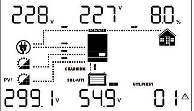 | 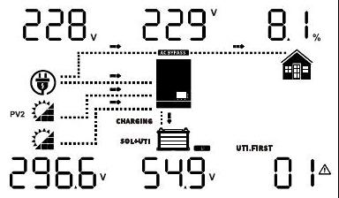 |
| (1)AC Input voltage (generator input) (If the AC input is only generator input, it means that what is displayed at this time is the input voltage of the generator. The current, power and frequency displayed after turning the page are also the input parameters of the generator, which will not be explained below.) <br> (2) Output voltage <br> (3) Load percentage <br> (4) Left: PV1 input voltage <br> Right: PV2 input voltage <br> (5) Battery voltage <br> (6) Warning or Fault code | 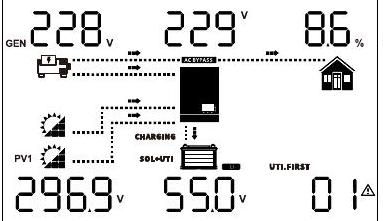 | 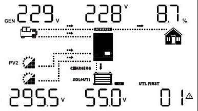 |
| (1) AC Input frequency <br> (2) Output frequency <br> (3) Load power <br> (4) PV energy sum <br> (5) Battery percentage <br> (6) Warning or Fault code | 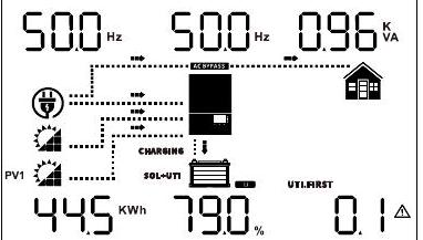 | / |
| (1) AC Input current <br> (2) Output current <br> (3) Load percentage <br> (4) Left: PV1 input current <br> Right: PV2 input current <br> (5) Battery charging current <br> (6) Warning or Fault code | 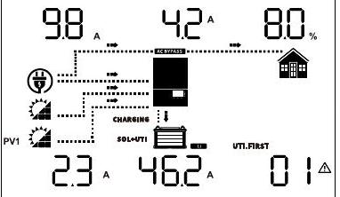 | 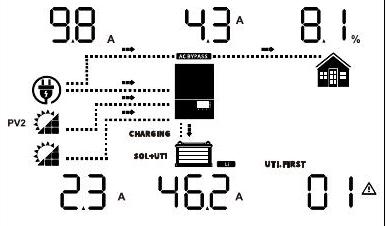 |
| (1) Feed to Grid current <br> (2) Output current <br> (3) Load percentage <br> (4) Left: PV1 input current <br> Right: PV2 input current <br> (5) Battery charging current <br> (6) Warning or Fault code | 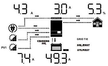 | 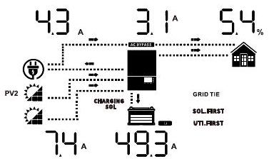 |
| (1) AC input power <br> (2) Output voltage <br> (3) Load power <br> (4) Left: PV1 input power <br> Right: PV2 input power <br> (5) Battery charging power <br> (6) Warning or Fault code | 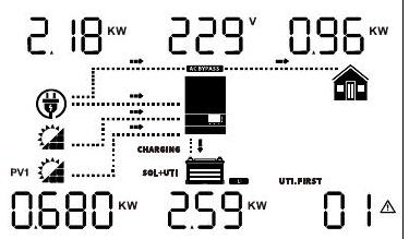 | 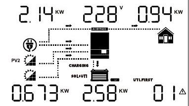 |
(1) Feed to Grid power
(2) Output voltage
(3) Load power
(4) Left: PV1 input power
Right: PV2 input power
(5) Battery charging power
(6) Warning or Fault code| (1) Feed to Grid power |
| :--- |
| (2) Output voltage |
| (3) Load power |
| (4) Left: PV1 input power |
| Right: PV2 input power |
| (5) Battery charging power |
| (6) Warning or Fault code |
(1) CT power
(2) CT active Power screen
(3) Loads and home load power
(4) Left: PV1 input power
Right: PV2 input power
(5) Battery charging power
(6) Warning or Fault code| (1) CT power |
| :--- |
| (2) CT active Power screen |
| (3) Loads and home load power |
| (4) Left: PV1 input power |
| Right: PV2 input power |
| (5) Battery charging power |
| (6) Warning or Fault code |
(1) CT power
(2) CT active Power screen
(3) Load power
(4) Left: PV1 temperature
Right: PV2 temperature
(5) Left: Ilc temperature
Right: Battery temperature
(6) Warning or Fault code| (1) CT power |
| :--- |
| (2) CT active Power screen |
| (3) Load power |
| (4) Left: PV1 temperature |
| Right: PV2 temperature |
| (5) Left: Ilc temperature |
| Right: Battery temperature |
| (6) Warning or Fault code |
(3) Load power PV1 temperature qquad\qquad Right: PV2 temperature (5) Left: Ilc temperature Right: Battery temperature (6) Warning or Fault code
(1) AC input power (2) Inverter temperature
(3) Load power PV1 temperature qquad Right: PV2 temperature (5) Left: Ilc temperature Right: Battery temperature (6) Warning or Fault code| (1) AC input power (2) Inverter temperature |
| :--- |
| (3) Load power PV1 temperature $\qquad$ Right: PV2 temperature (5) Left: Ilc temperature Right: Battery temperature (6) Warning or Fault code |
(1) Left: Today's energy feed to grid Right: Total energy feed to grid (2) Output frequency
(3) Left: Today's load energy Right: Total load energy (4) Left: Today's PV energy Right: Total PV energy (5) Left: Today's battery discharge energy Right: Total battery discharge energy (6)Indicate today's energy or total energy.
(1) Left: Today's energy feed to grid Right: Total energy feed to grid (2) Output frequency
(3) Left: Today's load energy Right: Total load energy (4) Left: Today's PV energy Right: Total PV energy (5) Left: Today's battery discharge energy Right: Total battery discharge energy (6)Indicate today's energy or total energy.| (1) Left: Today's energy feed to grid Right: Total energy feed to grid (2) Output frequency |
| :--- |
| (3) Left: Today's load energy Right: Total load energy (4) Left: Today's PV energy Right: Total PV energy (5) Left: Today's battery discharge energy Right: Total battery discharge energy (6)Indicate today's energy or total energy. |
Firmware version
(CPU1: 141-00-527; CPU2:142-00-529; CPU3:143-00-528)| Firmware version |
| :--- |
| (CPU1: 141-00-527; CPU2:142-00-529; CPU3:143-00-528) |
时间(2024 年 5 月 29 日 13:54:29)
Time
(13:54:29, May 29, 2024)
Time
(13:54:29, May 29, 2024)| Time |
| :--- |
| (13:54:29, May 29, 2024) |
/
"(1) Feed to Grid power
(2) Output voltage
(3) Load power
(4) Left: PV1 input power
Right: PV2 input power
(5) Battery charging power
(6) Warning or Fault code" https://cdn.mathpix.com/cropped/2025_07_03_e5427370408cc080841fg-11.jpg?height=217&width=372&top_left_y=144&top_left_x=587 https://cdn.mathpix.com/cropped/2025_07_03_e5427370408cc080841fg-11.jpg?height=223&width=378&top_left_y=138&top_left_x=967
"(1) CT power
(2) CT active Power screen
(3) Loads and home load power
(4) Left: PV1 input power
Right: PV2 input power
(5) Battery charging power
(6) Warning or Fault code" https://cdn.mathpix.com/cropped/2025_07_03_e5427370408cc080841fg-11.jpg?height=214&width=366&top_left_y=388&top_left_x=587 https://cdn.mathpix.com/cropped/2025_07_03_e5427370408cc080841fg-11.jpg?height=226&width=378&top_left_y=382&top_left_x=967
"(1) CT power
(2) CT active Power screen
(3) Load power
(4) Left: PV1 temperature
Right: PV2 temperature
(5) Left: Ilc temperature
Right: Battery temperature
(6) Warning or Fault code" "139^(x)quad[-t quad04|_(x_(n)):}
"
"
3 qquad i己
solvings 360." "130 xx1-1035 m
2 :-........
pv2
2
: sol+पn ◻ ,
sol first
Э
15. 365."
"(1) AC input power (2) Inverter temperature
(3) Load power PV1 temperature qquad Right: PV2 temperature (5) Left: Ilc temperature Right: Battery temperature (6) Warning or Fault code" https://cdn.mathpix.com/cropped/2025_07_03_e5427370408cc080841fg-11.jpg?height=258&width=381&top_left_y=889&top_left_x=588 https://cdn.mathpix.com/cropped/2025_07_03_e5427370408cc080841fg-11.jpg?height=258&width=402&top_left_y=889&top_left_x=946
"(1) Left: Today's energy feed to grid Right: Total energy feed to grid (2) Output frequency
(3) Left: Today's load energy Right: Total load energy (4) Left: Today's PV energy Right: Total PV energy (5) Left: Today's battery discharge energy Right: Total battery discharge energy (6)Indicate today's energy or total energy." https://cdn.mathpix.com/cropped/2025_07_03_e5427370408cc080841fg-11.jpg?height=221&width=384&top_left_y=1203&top_left_x=584 https://cdn.mathpix.com/cropped/2025_07_03_e5427370408cc080841fg-11.jpg?height=220&width=387&top_left_y=1209&top_left_x=962
"Firmware version
(CPU1: 141-00-527; CPU2:142-00-529; CPU3:143-00-528)" https://cdn.mathpix.com/cropped/2025_07_03_e5427370408cc080841fg-11.jpg?height=224&width=360&top_left_y=1488&top_left_x=590 https://cdn.mathpix.com/cropped/2025_07_03_e5427370408cc080841fg-11.jpg?height=224&width=378&top_left_y=1488&top_left_x=967
"Time
(13:54:29, May 29, 2024)" https://cdn.mathpix.com/cropped/2025_07_03_e5427370408cc080841fg-11.jpg?height=226&width=378&top_left_y=1756&top_left_x=587 /| (1) Feed to Grid power <br> (2) Output voltage <br> (3) Load power <br> (4) Left: PV1 input power <br> Right: PV2 input power <br> (5) Battery charging power <br> (6) Warning or Fault code | 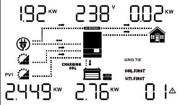 | 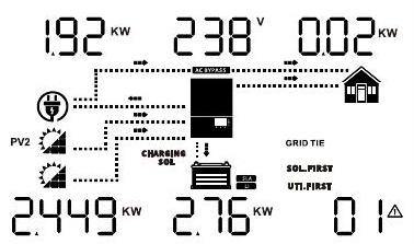 |
| :--- | :--- | :--- |
| (1) CT power <br> (2) CT active Power screen <br> (3) Loads and home load power <br> (4) Left: PV1 input power <br> Right: PV2 input power <br> (5) Battery charging power <br> (6) Warning or Fault code | 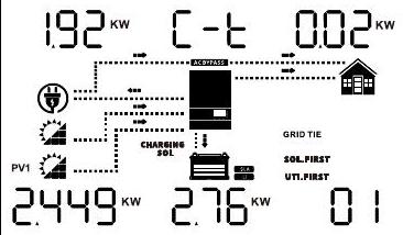 | 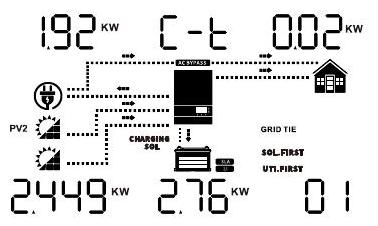 |
| (1) CT power <br> (2) CT active Power screen <br> (3) Load power <br> (4) Left: PV1 temperature <br> Right: PV2 temperature <br> (5) Left: Ilc temperature <br> Right: Battery temperature <br> (6) Warning or Fault code | $139^{x} \quad\left[-\left.t \quad 04\right\|_{x_{n}}\right.$ <br> " <br> " <br> 3 $\qquad$ i己 <br> solvings 360. | $130 \times 1-1035$ m <br> 2 :-........ <br> pv2 <br> 2 <br> : sol+पn $\square$ , <br> sol first <br> Э <br> 15. 365. |
| (1) AC input power (2) Inverter temperature <br> (3) Load power PV1 temperature $\qquad$ Right: PV2 temperature (5) Left: Ilc temperature Right: Battery temperature (6) Warning or Fault code | 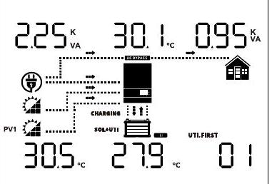 | 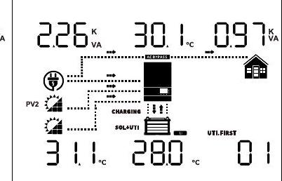 |
| (1) Left: Today's energy feed to grid Right: Total energy feed to grid (2) Output frequency <br> (3) Left: Today's load energy Right: Total load energy (4) Left: Today's PV energy Right: Total PV energy (5) Left: Today's battery discharge energy Right: Total battery discharge energy (6)Indicate today's energy or total energy. | 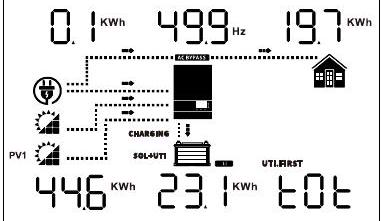 | 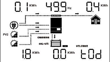 |
| Firmware version <br> (CPU1: 141-00-527; CPU2:142-00-529; CPU3:143-00-528) | 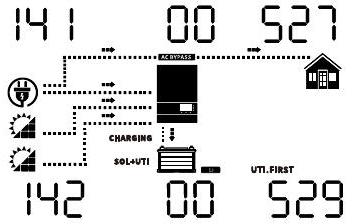 | 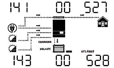 |
| Time <br> (13:54:29, May 29, 2024) | 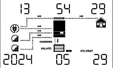 | / |
*Standby mode: The inverter is not turned on yet but at this time, the inverter can charge battery without AC output.
*Power saving mode: If enabled, the output of inverter will be off when connected load is pretty low or not detected.
Standby mode /Power saving mode
Note:
*Standby mode: The inverter is not turned on yet but at this time, the inverter can charge battery without AC output.
*Power saving mode: If enabled, the output of inverter will be off when connected load is pretty low or not detected.| Standby mode /Power saving mode |
| :--- |
| Note: |
| *Standby mode: The inverter is not turned on yet but at this time, the inverter can charge battery without AC output. |
| *Power saving mode: If enabled, the output of inverter will be off when connected load is pretty low or not detected. |
No output is supplied by the unit but it still can charge batteries. 该装置不提供输出,但它仍然可以为电池充电。
Charging by PV energy 光伏能源充电
故障模式 注: *故障模式:错误是由内部电路错误或外部原因引起的,如过热、输出短路等。
Fault mode
Note:
*Fault mode: Errors are caused by inside circuit error or external reasons such as over temperature, output short circuited and so on.
Fault mode
Note:
*Fault mode: Errors are caused by inside circuit error or external reasons such as over temperature, output short circuited and so on.| Fault mode |
| :--- |
| Note: |
| *Fault mode: Errors are caused by inside circuit error or external reasons such as over temperature, output short circuited and so on. |
PV energy can charge batteries. 光伏能源可以为电池充电。
Charging by PV energy 光伏能源充电
Line Mode
The unit will provide output power from the mains. It can also charge the battery at line mode. 该装置将提供来自市电的输出功率。它还可以在 line 模式下为电池充电。
Charging by PV energy 光伏能源充电
Feeds grid Mode Feeds 网格模式
Solar feeds to the grid or battery feeds to the grid 太阳能馈电到电网或电池馈送到电网
PV energy charges battery, PV energy provides power to the load and feeds remaining energy to the grid. PV Energy 为电池充电,PV Energy 为负载供电并将剩余能量馈送到电网。
Battery energy provides power to the load and feeds remaining energy to the grid. 电池能量为负载提供动力,并将剩余能量馈送到电网。
Battery Mode 电池模式
The unit will provide output power from battery and PV power. 该装置将提供来自电池的输出功率和光伏发电。
来自电池和 PV 能源的电力仅来自电池
Power from battery and PV energy
Power from battery only
Power from battery and PV energy
Power from battery only| Power from battery and PV energy |
| :--- |
| Power from battery only |
Operation mode Description LCD display
"Standby mode /Power saving mode
Note:
*Standby mode: The inverter is not turned on yet but at this time, the inverter can charge battery without AC output.
*Power saving mode: If enabled, the output of inverter will be off when connected load is pretty low or not detected." No output is supplied by the unit but it still can charge batteries. Charging by PV energy
"Fault mode
Note:
*Fault mode: Errors are caused by inside circuit error or external reasons such as over temperature, output short circuited and so on." PV energy can charge batteries. Charging by PV energy
Line Mode The unit will provide output power from the mains. It can also charge the battery at line mode. Charging by PV energy
Feeds grid Mode Solar feeds to the grid or battery feeds to the grid PV energy charges battery, PV energy provides power to the load and feeds remaining energy to the grid.
Battery energy provides power to the load and feeds remaining energy to the grid.
Battery Mode The unit will provide output power from battery and PV power. "Power from battery and PV energy
Power from battery only"| Operation mode | Description | LCD display |
| :--- | :--- | :--- |
| Standby mode /Power saving mode <br> Note: <br> *Standby mode: The inverter is not turned on yet but at this time, the inverter can charge battery without AC output. <br> *Power saving mode: If enabled, the output of inverter will be off when connected load is pretty low or not detected. | No output is supplied by the unit but it still can charge batteries. | Charging by PV energy |
| Fault mode <br> Note: <br> *Fault mode: Errors are caused by inside circuit error or external reasons such as over temperature, output short circuited and so on. | PV energy can charge batteries. | Charging by PV energy |
| Line Mode | The unit will provide output power from the mains. It can also charge the battery at line mode. | Charging by PV energy |
| Feeds grid Mode | Solar feeds to the grid or battery feeds to the grid | PV energy charges battery, PV energy provides power to the load and feeds remaining energy to the grid. |
| | | Battery energy provides power to the load and feeds remaining energy to the grid. |
| Battery Mode | The unit will provide output power from battery and PV power. | Power from battery and PV energy <br> Power from battery only |
4.3 LCD parameter setting 4.3 LCD 参数设置
4.3.1General settings 4.3.1常规设置
After pressing and holding ENTER button for 3 seconds,the unit will enter setting mode.Press"UP"or"DOWN" 长按 ENTER 键 3 秒后,设备进入设置模式。
button to select setting programs.Then press"ENTER"button to confirm the selection or ESC button to exit. 按钮选择设置程序,然后按“ENTER”按钮确认选择,或按 ESC 按钮退出。
Program 程序
Description 描述
Setting Option 设置选项
TYO:自耗(默认) 5ELF E 4 G nga
TYO:Self-consumption(default)
5ELF
E 4 G
nga
TYO:Self-consumption(default)
5ELF
E 4 G
nga| TYO:Self-consumption(default) |
| :--- |
| 5ELF |
| E 4 G |
| nga |
When the PV power is sufficient,the PV energy first prioritizes supplying power to the off grid load.Any excess energy is used to charge the battery,and the PV energy is not fed into the grid.Meanwhile,the on- grid load is powered by the utility power.Conversely,When the PV used to supply p ower to the off-grid load,and the on-grid load is powered by the grid power.In the event of grid power outage th energy and battery discharge together to supply power to the PV grid loads. grid loads. 当光伏发电量充足时,光伏能源首先优先向离网负载供电,多余的能量用于给电池充电,光伏发电没有送入电网,同时,并网负载由市电供电,相反,当光伏发电用于向离网负载供电时,power.In 电网停电时,能源由电网供电和电池放电一起为光伏电网负载供电。电网负载。
Quick Settings 快捷设置
*After setting TY1,TY2, or TY3,the initial default values of some settings 99 will be changed.Users can set them based on help users quickly set the help users quick *设置 TY1、TY2 或 TY3 后,部分设置 99 的初始默认值会发生变化,用户可以根据帮助用户快速设置帮助用户来设置它们
TY1:负载第一模式 LOd.F tyl 9^(@)\stackrel{\circ}{9}
TY1:Load First Mode LOd.F tyl
9^(@)\stackrel{\circ}{9}
TY1:Load First Mode LOd.F tyl
9^(@)| TY1:Load First Mode LOd.F tyl |
| :--- |
| $\stackrel{\circ}{9}$ |
Program 程序
01
03
14
55
67
69
Value 价值
SUB
UPS
SNU
LBU
ENA
12 KW 12 千瓦
Program 程序
71
76
78
79
80
Value 价值
ENA
ENA
12 KW 12 千瓦
DIS
24 KW 24 千瓦
"TY1:Load First Mode LOd.F tyl
9^(@)"
Program 01 03 14 55 67 69
Value SUB UPS SNU LBU ENA 12 KW
Program 71 76 78 79 80
Value ENA ENA 12 KW DIS 24 KW | TY1:Load First Mode LOd.F tyl <br> $\stackrel{\circ}{9}$ | | | | | | |
| :--- | :--- | :--- | :--- | :--- | :--- | :--- |
| Program | 01 | 03 | 14 | 55 | 67 | 69 |
| Value | SUB | UPS | SNU | LBU | ENA | 12 KW |
| | | | | | | |
| Program | 71 | 76 | 78 | 79 | 80 | |
| Value | ENA | ENA | 12 KW | DIS | 24 KW | |
When PV power is sufficient,the PV energy first prioritizes supplying power to the on/off grid load,the excess PV energy is used to charge the battery,after that any surplus PV energy will fed into the grid. Conversely,When PV power is insufficient,both the PV energy and battery energy are used to supply power to the on/off-grid load,but the battery energy will not feed into the grid. 当光伏发电量充足时,光伏能源首先优先为并网/离网负载供电,多余的光伏能源用于为电池充电,然后任何多余的光伏能源都将馈入电网。相反,当光伏发电量不足时,光伏能源和电池能源都用于为并网/离网负载供电,但电池能源不会馈入电网。
installation method of the external CT sensor please refer to chapter 3.8 CT Connection. 外置 CT 传感器的安装方法请参考第 3.8 章 CT 连接。
TY2:Battery First Mode TY2:电池优先模式
BRE.F BRE.F 公司
EUC
Brogram 01 03 14 55 67 值 SUB UPS SNU BLU ENA 12 KW 程序 71 76 78 79 80 值 ENA ENA 12 KW DIS 24 KW
Brogram
01
03
14
55
67
Value
SUB
UPS
SNU
BLU
ENA
12 KW
Program
71
76
78
79
80
Value
ENA
ENA
12 KW
DIS
24 KW
Brogram 01 03 14 55 67
Value SUB UPS SNU BLU ENA
12 KW
Program 71 76 78 79 80
Value ENA ENA 12 KW DIS 24 KW | Brogram | 01 | 03 | 14 | 55 | 67 | |
| :---: | :---: | :---: | :---: | :---: | :---: | :---: |
| Value | SUB | UPS | SNU | BLU | ENA | |
| 12 KW | | | | | | |
| Program | 71 | 76 | 78 | 79 | 80 | |
| Value | ENA | ENA | 12 KW | DIS | 24 KW | |
TY2:Battery First Mode
BRE.F EUC
"Brogram 01 03 14 55 67
Value SUB UPS SNU BLU ENA
12 KW
Program 71 76 78 79 80
Value ENA ENA 12 KW DIS 24 KW " | TY2:Battery First Mode | | | | | | |
| :---: | :---: | :---: | :---: | :---: | :---: | :---: |
| BRE.F | EUC | | | | | |
| Brogram 01 03 14 55 67 <br> Value SUB UPS SNU BLU ENA <br> 12 KW <br> Program 71 76 78 79 80 <br> Value ENA ENA 12 KW DIS 24 KW | | | | | | |
When the PV power is sufficient,the PV energy gives priority to charging the battery.After that the excess PV energy is used to supply power to the on/off-grid load,and any excess surplus PV energy is fed into the grid.Conversely,when the PV power is insufficient,both the PV energy and the grid energy to supply power to the on/ofi-grid load.In the together to power the off grid load,but the battery energy will not feed into the grid. 当光伏发电量充足时,光伏能源优先给电池充电,之后多余的光伏能源用于为并网/离网负载供电,多余的光伏能源将馈入电网,相反,当光伏发电量不足时,光伏能源和向并网供电的电网能源 load.In 一起为离网负载供电,但电池能量不会馈入网格。
External CT 外部 CT
External CT sensor required for this mode,the installation method of the external CT sensor please refer to chapter 3.8 CT Connection. 此模式需要外接 CT 传感器,外接 CT 传感器的安装方法请参考第 3.8 章 CT 连接。
TY3:导出限制模式 nin ヒリコ 09:更改以下设置的默认值,如下所示:
TY3:Export Limit Mode nin ヒリコ 09:
Change the default values of the following settings as follows:
TY3:Export Limit Mode nin ヒリコ 09:
Change the default values of the following settings as follows:| TY3:Export Limit Mode nin ヒリコ 09: |
| :--- |
| Change the default values of the following settings as follows: |
计划价值
Program
Value
Program
Value| Program |
| :---: |
| Value |
01
03
14
55
67
69
Value 价值
SUB
UPS
SNU
LBU
ENA
12 KW 12 千瓦
Program 程序
71
76
78
79
80
Value 价值
ENA
ENA
0KW
DIS
24 KW 24 千瓦
When PV power is sufficient,the PV energy first prioritizes supplying power to the on/off grid load.Any surplus energy is used to charge the battery,and the excess PV energy is not fed into the grid.Conversely, when PV power is insufficient,both the PV energy and the battery discharge together to power the on/off grid load.However,the battery energy is not fed into the grid.External CT sensor required for this mode, the installation method of the external CT sensor please refer to chapter 3.8 CT Connection. 当光伏发电量充足时,光伏能源首先优先为并网/离网负载供电,任何多余的能量都用于给电池充电,多余的光伏能源不会馈入电网。相反,当光伏发电量不足时,光伏能源和电池一起放电,为开/离网负载供电,但是,电池能量没有馈入电网,这种模式需要外部 CT 传感器,安装方法外部 CT 传感器请参考第 3.8 章 CT 连接。
01
Output source priority:To configure load power source priority. (After program 67 are enabled,this program is fixed SUB and cannot be set.) 输出源优先级:设置负载电源优先级。(程序 67 启用后,该程序固定为 SUB,无法设置。
Solar energy provides power to the loads as first priority. If solar energy is not sufficient to power all connected loads, batteryenergy will supply power the loads at the same time. Utility provides power to the loads only when any one condition happens: -Solar energy is not available
-Battery voltage drops to either low-level warning voltage or the setting point in program 12.
Solar energy provides power to the loads as first priority. If solar energy is not sufficient to power all connected loads, batteryenergy will supply power the loads at the same time. Utility provides power to the loads only when any one condition happens: -Solar energy is not available
-Battery voltage drops to either low-level warning voltage or the setting point in program 12.| Solar energy provides power to the loads as first priority. If solar energy is not sufficient to power all connected loads, batteryenergy will supply power the loads at the same time. Utility provides power to the loads only when any one condition happens: -Solar energy is not available |
| :--- |
| -Battery voltage drops to either low-level warning voltage or the setting point in program 12. |
Utility first 实用工具优先
OPPY
公用事业公司将优先为负载供电。太阳能和电池能源仅在市电不可用时为负载供电。
Utility will provide power to the loads as first priority.
Solar and battery energy will provide power to the loads only when utility power is not available.
Utility will provide power to the loads as first priority.
Solar and battery energy will provide power to the loads only when utility power is not available.| Utility will provide power to the loads as first priority. |
| :--- |
| Solar and battery energy will provide power to the loads only when utility power is not available. |
Solar energy provides power to the loads as first priority.
If solar energy is not sufficient to power all connected loads,battery will supply power to the loads at the same time.
Utility provides power to the loads only when battery voltage drops to either low-level warning voltage or the setting point in program 12.
Solar energy provides power to the loads as first priority.
If solar energy is not sufficient to power all connected loads,battery will supply power to the loads at the same time.
Utility provides power to the loads only when battery voltage drops to either low-level warning voltage or the setting point in program 12.| Solar energy provides power to the loads as first priority. |
| :--- |
| If solar energy is not sufficient to power all connected loads,battery will supply power to the loads at the same time. |
| Utility provides power to the loads only when battery voltage drops to either low-level warning voltage or the setting point in program 12. |
Solar energy provides power to the loads as first priority.
If solar energy is not sufficient to power all connected loads,solar and utility will power loads at the same time.
Battery provides power to the loads only when solar energy is not sufficient and there is no utility.
Solar energy provides power to the loads as first priority.
If solar energy is not sufficient to power all connected loads,solar and utility will power loads at the same time.
Battery provides power to the loads only when solar energy is not sufficient and there is no utility.| Solar energy provides power to the loads as first priority. |
| :--- |
| If solar energy is not sufficient to power all connected loads,solar and utility will power loads at the same time. |
| Battery provides power to the loads only when solar energy is not sufficient and there is no utility. |
"TY3:Export Limit Mode nin ヒリコ 09:
Change the default values of the following settings as follows:"
"Program
Value" 01 03 14 55 67 69
Value SUB UPS SNU LBU ENA 12 KW
Program 71 76 78 79 80
Value ENA ENA 0KW DIS 24 KW
When PV power is sufficient,the PV energy first prioritizes supplying power to the on/off grid load.Any surplus energy is used to charge the battery,and the excess PV energy is not fed into the grid.Conversely, when PV power is insufficient,both the PV energy and the battery discharge together to power the on/off grid load.However,the battery energy is not fed into the grid.External CT sensor required for this mode, the installation method of the external CT sensor please refer to chapter 3.8 CT Connection.
01 Output source priority:To configure load power source priority. (After program 67 are enabled,this program is fixed SUB and cannot be set.) Solar first https://cdn.mathpix.com/cropped/2025_07_03_e5427370408cc080841fg-12.jpg?height=71&width=345&top_left_y=753&top_left_x=2237
"Solar energy provides power to the loads as first priority. If solar energy is not sufficient to power all connected loads, batteryenergy will supply power the loads at the same time. Utility provides power to the loads only when any one condition happens: -Solar energy is not available
-Battery voltage drops to either low-level warning voltage or the setting point in program 12."
Utility first OPPY
"Utility will provide power to the loads as first priority.
Solar and battery energy will provide power to the loads only when utility power is not available."
SBU priority(default) 56L ""unst
00^(@)"
"Solar energy provides power to the loads as first priority.
If solar energy is not sufficient to power all connected loads,battery will supply power to the loads at the same time.
Utility provides power to the loads only when battery voltage drops to either low-level warning voltage or the setting point in program 12."
SUB priority https://cdn.mathpix.com/cropped/2025_07_03_e5427370408cc080841fg-12.jpg?height=84&width=334&top_left_y=1647&top_left_x=2239
"Solar energy provides power to the loads as first priority.
If solar energy is not sufficient to power all connected loads,solar and utility will power loads at the same time.
Battery provides power to the loads only when solar energy is not sufficient and there is no utility." | | | TY3:Export Limit Mode nin ヒリコ 09: <br> Change the default values of the following settings as follows: | | | | | | |
| :--- | :--- | :--- | :--- | :--- | :--- | :--- | :--- | :--- |
| | | Program <br> Value | 01 | 03 | 14 | 55 | 67 | 69 |
| | | Value | SUB | UPS | SNU | LBU | ENA | 12 KW |
| | | Program | 71 | 76 | 78 | 79 | 80 | |
| | | Value | ENA | ENA | 0KW | DIS | 24 KW | |
| | | When PV power is sufficient,the PV energy first prioritizes supplying power to the on/off grid load.Any surplus energy is used to charge the battery,and the excess PV energy is not fed into the grid.Conversely, when PV power is insufficient,both the PV energy and the battery discharge together to power the on/off grid load.However,the battery energy is not fed into the grid.External CT sensor required for this mode, the installation method of the external CT sensor please refer to chapter 3.8 CT Connection. | | | | | | |
| 01 | Output source priority:To configure load power source priority. (After program 67 are enabled,this program is fixed SUB and cannot be set.) | Solar first | | |  | | | |
 | | Solar energy provides power to the loads as first priority. If solar energy is not sufficient to power all connected loads, batteryenergy will supply power the loads at the same time. Utility provides power to the loads only when any one condition happens: -Solar energy is not available <br> -Battery voltage drops to either low-level warning voltage or the setting point in program 12. | | | |
| | | Utility first | | | OPPY | | | |
| | | | | | Utility will provide power to the loads as first priority. <br> Solar and battery energy will provide power to the loads only when utility power is not available. | | | |
| | | SBU priority(default) | | | 56L | | "unst <br> $00^{\circ}$ | |
| | | | | | Solar energy provides power to the loads as first priority. <br> If solar energy is not sufficient to power all connected loads,battery will supply power to the loads at the same time. <br> Utility provides power to the loads only when battery voltage drops to either low-level warning voltage or the setting point in program 12. | | | |
| | | SUB priority | | | 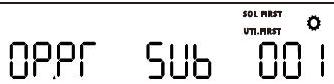 | | | |
 | | Solar energy provides power to the loads as first priority. <br> If solar energy is not sufficient to power all connected loads,solar and utility will power loads at the same time. <br> Battery provides power to the loads only when solar energy is not sufficient and there is no utility. | | | |
02
Maximum charging current: set total charging current for solar and utility chargers. 最大充电电流:设置太阳能和市电充电器的总充电电流。
(Max.charging current == utility charging current + solar charging current) (If LI is selected in Program 5,this program can't be set up)
[HE.I ICO . 00 D'
SPE 12000 ES:Default 120A,0A~250A Settable.
SPE 10000 ES:Default 120A,0A~220A Settable.
SPE 8000 ES:Default 120A,0A~190A Settable.
(Max.charging current = utility charging current + solar charging current) (If LI is selected in Program 5,this program can't be set up)| [HE.I ICO . 00 D' |
| :--- |
| SPE 12000 ES:Default 120A,0A~250A Settable. |
| SPE 10000 ES:Default 120A,0A~220A Settable. |
| SPE 8000 ES:Default 120A,0A~190A Settable. |
| (Max.charging current $=$ utility charging current + solar charging current) (If LI is selected in Program 5,this program can't be set up) |
03
AC input voltage range (After program 67 are enabled,this program is fixed UPS and cannot be set). 交流输入电压范围(程序 67 启用后,该程序为固定 UPS,无法设置)。
设备(默认) RLU RPL BOI 如果选中,可接受的交流输入电压 tage 范围将在:90~280VAC
Appliance(default)
RLU RPL BOI
If selected,acceptable AC input voltage range will be within: 90~280VAC
Appliance(default)
RLU RPL BOI
If selected,acceptable AC input voltage range will be within: 90~280VAC| Appliance(default) |
| :--- |
| RLU RPL BOI |
| If selected,acceptable AC input voltage range will be within: 90~280VAC |
UPS R[U UPS 003 如果选择,可接受的交流输入电压范围将在:170~280VAC
UPS
R[U UPS 003
If selected,acceptable AC input voltage range will be within: 170~280VAC
UPS
R[U UPS 003
If selected,acceptable AC input voltage range will be within: 170~280VAC| UPS |
| :--- |
| R[U UPS 003 |
| If selected,acceptable AC input voltage range will be within: 170~280VAC |
04
Power saving mode enable/disable 省电模式启用/禁用
保存模式禁用(默认) 5RUE di 5 ROLi 如果禁用,无论连接的负载是低还是高,逆变器输出的开/关状态都不会受到影响。
Saving mode disable(default)
5RUE di 5 ROLi
If disabled,no matter connected load is low or high,the on/off status of inverter output will not be effected.
Saving mode disable(default)
5RUE di 5 ROLi
If disabled,no matter connected load is low or high,the on/off status of inverter output will not be effected.| Saving mode disable(default) |
| :--- |
| 5RUE di 5 ROLi |
| If disabled,no matter connected load is low or high,the on/off status of inverter output will not be effected. |
保存模式启用 SRUE ERR 或 如果启用,当连接的负载很低或未检测到时,逆变器的输出将关闭。
Saving mode enable
SRUE ERR ORபீ
If enabled,the output of inverter will be off when connected load is pretty low or not detected.
Saving mode enable
SRUE ERR ORபீ
If enabled,the output of inverter will be off when connected load is pretty low or not detected.| Saving mode enable |
| :--- |
| SRUE ERR ORபீ |
| If enabled,the output of inverter will be off when connected load is pretty low or not detected. |
05
Battery type 电池类型
AGM(default)-Suitable for lead-acid battery AGM(默认)-适用于铅酸电池
无法设置的项目 19 20 21 默认 56.4 V 54 V 42 V
Items that cannot be set
19
20
21
default
56.4 V
54 V
42 V
Items that cannot be set 19 20 21
default 56.4 V 54 V 42 V| Items that cannot be set | 19 | 20 | 21 |
| :--- | :--- | :--- | :--- |
| default | 56.4 V | 54 V | 42 V |
Flooded-Suitable for lead-acid battery or flood battery 富液式 - 适用于铅酸电池或富液式电池
无法设置的项目:19 20 21 默认 58.4 V 56 V 42 V
Items that cannot be set:
19
20
21
default
58.4 V
56 V
42 V
Items that cannot be set: 19 20 21
default 58.4 V 56 V 42 V| Items that cannot be set: | 19 | 20 | 21 |
| :--- | :--- | :--- | :--- |
| default | 58.4 V | 56 V | 42 V |
可以设置默认 Set requirements 的项目:
Items that default
Set requirements can be set:
Items that default
Set requirements can be set:| Items that default |
| :--- |
| Set requirements can be set: |
02
0A~250A 0A~250A
11
0A~250A 0A~250A
12
44∼51.2V44 \sim 51.2 \mathrm{~V}
<13 setting value <13 设置值
13
48∼58.0V48 \sim 58.0 \mathrm{~V}
02 Maximum charging current: set total charging current for solar and utility chargers. "[HE.I ICO . 00 D'
SPE 12000 ES:Default 120A,0A~250A Settable.
SPE 10000 ES:Default 120A,0A~220A Settable.
SPE 8000 ES:Default 120A,0A~190A Settable.
(Max.charging current = utility charging current + solar charging current) (If LI is selected in Program 5,this program can't be set up)"
03 AC input voltage range (After program 67 are enabled,this program is fixed UPS and cannot be set). "Appliance(default)
RLU RPL BOI
If selected,acceptable AC input voltage range will be within: 90~280VAC"
"UPS
R[U UPS 003
If selected,acceptable AC input voltage range will be within: 170~280VAC"
04 Power saving mode enable/disable "Saving mode disable(default)
5RUE di 5 ROLi
If disabled,no matter connected load is low or high,the on/off status of inverter output will not be effected."
"Saving mode enable
SRUE ERR ORபீ
If enabled,the output of inverter will be off when connected load is pretty low or not detected."
05 Battery type AGM(default)-Suitable for lead-acid battery
"Items that cannot be set 19 20 21
default 56.4 V 54 V 42 V"
Flooded-Suitable for lead-acid battery or flood battery
https://cdn.mathpix.com/cropped/2025_07_03_e5427370408cc080841fg-13.jpg?height=65&width=381&top_left_y=1480&top_left_x=552
"Items that cannot be set: 19 20 21
default 58.4 V 56 V 42 V"
"Items that default
Set requirements can be set:"
02 0A~250A
11 0A~250A
12 44∼51.2V <13 setting value
13 48∼58.0V | 02 | Maximum charging current: set total charging current for solar and utility chargers. | [HE.I ICO . 00 D' <br> SPE 12000 ES:Default 120A,0A~250A Settable. <br> SPE 10000 ES:Default 120A,0A~220A Settable. <br> SPE 8000 ES:Default 120A,0A~190A Settable. <br> (Max.charging current $=$ utility charging current + solar charging current) (If LI is selected in Program 5,this program can't be set up) | | | |
| :--- | :--- | :--- | :--- | :--- | :--- |
| 03 | AC input voltage range (After program 67 are enabled,this program is fixed UPS and cannot be set). | Appliance(default) <br> RLU RPL BOI <br> If selected,acceptable AC input voltage range will be within: 90~280VAC | | | |
| | | UPS <br> R[U UPS 003 <br> If selected,acceptable AC input voltage range will be within: 170~280VAC | | | |
| 04 | Power saving mode enable/disable | Saving mode disable(default) <br> 5RUE di 5 ROLi <br> If disabled,no matter connected load is low or high,the on/off status of inverter output will not be effected. | | | |
| | | Saving mode enable <br> SRUE ERR ORபீ <br> If enabled,the output of inverter will be off when connected load is pretty low or not detected. | | | |
| 05 | Battery type | AGM(default)-Suitable for lead-acid battery | | | |
| | | | | | |
| | | Items that cannot be set 19 20 21 <br> default 56.4 V 54 V 42 V | | | |
| | | | | | |
| | | | | | |
| | | | | | |
| | | | | | |
| | | | | | |
| | | | | | |
| | | Flooded-Suitable for lead-acid battery or flood battery | | | |
| | |  | | | |
| | | Items that cannot be set: 19 20 21 <br> default 58.4 V 56 V 42 V | | | |
| | | | | | |
| | | Items that default <br> Set requirements can be set: | | | |
| | | 02 | 0A~250A | | |
| | | 11 | 0A~250A | | |
| | | 12 | $44 \sim 51.2 \mathrm{~V}$ | | <13 setting value |
| | | 13 | $48 \sim 58.0 \mathrm{~V}$ | | |
锂电池(仅适用于与 BMS 通信通信时) bRLE LI OBS
Lithium(only suitable when communicated with BMS communication)
bRLE LI OBS
Lithium(only suitable when communicated with BMS communication)
bRLE LI OBS| Lithium(only suitable when communicated with BMS communication) |
| :--- |
| bRLE LI OBS |
无法设置的项目:02 19 20
Items that cannot be set:
02
19
20
Items that cannot be set:
02
19
20| Items that cannot be set: |
| :--- |
| 02 |
| 19 |
| 20 |
Items that can be set: 可设置的项目:
Set range 设置范围
Set requirements 设置要求
11
0A~250A 0A~250A
12
10\%~95\% 10\%~95\%
<13 setting value <13 设置值
13
15\%~100\% 15\%~100\%
21
5\%~50\% 5\%~50\%
<12 setting value <12 设置值
用户定义 - 适用于铅酸电池,电池参数可手动设置 BRE USE OGE
User-Defined-Suitable for lead-acid battery,battery parameters can be set manually
BRE USE OGE
User-Defined-Suitable for lead-acid battery,battery parameters can be set manually
BRE USE OGE| User-Defined-Suitable for lead-acid battery,battery parameters can be set manually |
| :--- |
| BRE USE OGE |
User-Defined 2 (suitable when lithium battery without BMS communication or communication protocol not matched with the inverter,battery parameters can be set manually)
BREE UE OCE
User-Defined 2 (suitable when lithium battery without BMS communication or communication protocol not matched with the inverter,battery parameters can be set manually)
BREE UE OCE| User-Defined 2 (suitable when lithium battery without BMS communication or communication protocol not matched with the inverter,battery parameters can be set manually) |
| :--- |
| BREE UE OCE |
Note:If setting value in Program 02 is smaller than that in Program 11,the inverter will apply charging current from Program 02 for utility charger
REI 60^
EETI L0 0 1
SPE 12000 ES:Default 60A(utility)/40A(generator),0A~250A Settable.
SPE 10000 ES:Default 60A(utility)/40A(generator),0A~220A Settable.
SPE 8000 ES:Default 60A(utility)/40A(generator),0A~190A Settable.
Note:If setting value in Program 02 is smaller than that in Program 11,the inverter will apply charging current from Program 02 for utility charger| REI 60^ |
| :--- |
| EETI L0 0 1 |
| SPE 12000 ES:Default 60A(utility)/40A(generator),0A~250A Settable. |
| SPE 10000 ES:Default 60A(utility)/40A(generator),0A~220A Settable. |
| SPE 8000 ES:Default 60A(utility)/40A(generator),0A~190A Settable. |
| Note:If setting value in Program 02 is smaller than that in Program 11,the inverter will apply charging current from Program 02 for utility charger |
12
Setting voltage point back to utility source when selecting "SBU priority"or"Solar first" in program 01 在程序 01 中选择“SBU 优先”或“太阳能优先”时,将电压点设置回市电电源
[10BH][10BH2]
The default value and adjustable range vary in different Battery type,please refer to program 5 for details 不同电池类型的默认值和可调范围不同,详见程序 5
[10BH][10BH2]
The default value and adjustable range vary in different Battery type,please refer to program 5 for details| <smiles>[10BH][10BH2]</smiles> |
| :--- |
| The default value and adjustable range vary in different Battery type,please refer to program 5 for details |
13
Setting voltage point back to battery mode when selecting "SBU priority"or"Solar first" in program 01 在程序 01 中选择“SBU 优先”或“太阳能优先”时将电压点设置回电池模式
The default value and adjustable range vary in different Battery type,please refer to program 5 for details 不同电池类型的默认值和可调范围不同,详见程序 5
(After program 67 are enabled,this program is fixed SUN and cannot be set.)
Charger source priority:To configure charger source priority.
(After program 67 are enabled,this program is fixed SUN and cannot be set.)| Charger source priority:To configure charger source priority. |
| :--- |
| (After program 67 are enabled,this program is fixed SUN and cannot be set.) |
If this off grid solar inverter is working in Line,Standby or Fault mode,charger source can be programmed as below: 如果此离网太阳能逆变器在在线、待机或故障模式下工作,则可以按以下方式对充电器电源进行编程:
Solar first(default) Solar first(太阳能优先)
Solar energy will charge battery as first priority.Utility will charge battery only when solar energy is not available. 太阳能将优先为电池充电。公用事业公司仅在太阳能不可用时才为电池充电。
Solar and Utility 太阳能和公用事业
Solar energy and utility will both charge battery. 太阳能和公用事业都可以为电池充电。
Only Solar 仅太阳能
Solar energy will be the only charger source no matter utility is available or not. 无论是否有公用事业,太阳能都将是唯一的充电来源。
If this PV Hybrid Inverter is working in Battery mode or Power saving mode, only solar energy can charge battery.Solar energy will charge battery if it's available and sufficient. 如果此光伏混合逆变器在电池模式或省电模式下工作,则只有太阳能可以为电池充电。
15
Alarm control 警报控制
Alarm on(default) 闹钟开启(默认)
Alarm off 闹钟关闭
16
Backlight control 背光控制
Backlight on 背光开启
Backlight off(default) 背光关闭(默认)
17
Beeps while primary source is interrupted 主源中断时发出蜂鸣声
Alarm on(default) 闹钟开启(默认)
Alarm off 闹钟关闭
18
过载旁路:启用后,如果电池模式下发生过载,设备将切换到线路模式。
Overload bypass:
When enabled,the unit will transfer to line mode if overload occurs in battery mode.
Overload bypass:
When enabled,the unit will transfer to line mode if overload occurs in battery mode.| Overload bypass: |
| :--- |
| When enabled,the unit will transfer to line mode if overload occurs in battery mode. |
Default 56.4 V , 48.0 V ~58.4V Settable 默认 56.4 V、48.0 V ~58.4V 可设置
20
Floating charging voltage. 浮动充电电压。
Default 54.0 V , 48.0 V ~58.4V Settable 默认 54.0 V、48.0 V ~58.4V 可设置
11 Maximum utility \&Generator charging current "REI 60^
EETI L0 0 1
SPE 12000 ES:Default 60A(utility)/40A(generator),0A~250A Settable.
SPE 10000 ES:Default 60A(utility)/40A(generator),0A~220A Settable.
SPE 8000 ES:Default 60A(utility)/40A(generator),0A~190A Settable.
Note:If setting value in Program 02 is smaller than that in Program 11,the inverter will apply charging current from Program 02 for utility charger"
12 Setting voltage point back to utility source when selecting "SBU priority"or"Solar first" in program 01 "[10BH][10BH2]
The default value and adjustable range vary in different Battery type,please refer to program 5 for details"
13 Setting voltage point back to battery mode when selecting "SBU priority"or"Solar first" in program 01 The default value and adjustable range vary in different Battery type,please refer to program 5 for details
14 "Charger source priority:To configure charger source priority.
(After program 67 are enabled,this program is fixed SUN and cannot be set.)" If this off grid solar inverter is working in Line,Standby or Fault mode,charger source can be programmed as below:
Solar first(default) Solar energy will charge battery as first priority.Utility will charge battery only when solar energy is not available.
Solar and Utility Solar energy and utility will both charge battery.
Only Solar Solar energy will be the only charger source no matter utility is available or not.
If this PV Hybrid Inverter is working in Battery mode or Power saving mode, only solar energy can charge battery.Solar energy will charge battery if it's available and sufficient.
15 Alarm control Alarm on(default) Alarm off
16 Backlight control Backlight on Backlight off(default)
17 Beeps while primary source is interrupted Alarm on(default) Alarm off
18 "Overload bypass:
When enabled,the unit will transfer to line mode if overload occurs in battery mode." Bypass disable(default) "Bypass enable
bup"
19 C.V.charging voltage. Default 56.4 V , 48.0 V ~58.4V Settable
20 Floating charging voltage. Default 54.0 V , 48.0 V ~58.4V Settable | 11 | Maximum utility \&Generator charging current | REI 60^ <br> EETI L0 0 1 <br> SPE 12000 ES:Default 60A(utility)/40A(generator),0A~250A Settable. <br> SPE 10000 ES:Default 60A(utility)/40A(generator),0A~220A Settable. <br> SPE 8000 ES:Default 60A(utility)/40A(generator),0A~190A Settable. <br> Note:If setting value in Program 02 is smaller than that in Program 11,the inverter will apply charging current from Program 02 for utility charger | |
| :--- | :--- | :--- | :--- |
| 12 | Setting voltage point back to utility source when selecting "SBU priority"or"Solar first" in program 01 | <smiles>[10BH][10BH2]</smiles> <br> The default value and adjustable range vary in different Battery type,please refer to program 5 for details | |
| 13 | Setting voltage point back to battery mode when selecting "SBU priority"or"Solar first" in program 01 | The default value and adjustable range vary in different Battery type,please refer to program 5 for details | |
| 14 | Charger source priority:To configure charger source priority. <br> (After program 67 are enabled,this program is fixed SUN and cannot be set.) | If this off grid solar inverter is working in Line,Standby or Fault mode,charger source can be programmed as below: | |
| | | Solar first(default) | Solar energy will charge battery as first priority.Utility will charge battery only when solar energy is not available. |
| | | Solar and Utility | Solar energy and utility will both charge battery. |
| | | Only Solar | Solar energy will be the only charger source no matter utility is available or not. |
| | | If this PV Hybrid Inverter is working in Battery mode or Power saving mode, only solar energy can charge battery.Solar energy will charge battery if it's available and sufficient. | |
| 15 | Alarm control | Alarm on(default) | Alarm off |
| 16 | Backlight control | Backlight on | Backlight off(default) |
| 17 | Beeps while primary source is interrupted | Alarm on(default) | Alarm off |
| 18 | Overload bypass: <br> When enabled,the unit will transfer to line mode if overload occurs in battery mode. | Bypass disable(default) | Bypass enable <br> bup |
| 19 | C.V.charging voltage. | Default 56.4 V , 48.0 V ~58.4V Settable | |
| 20 | Floating charging voltage. | Default 54.0 V , 48.0 V ~58.4V Settable | |
The default value and adjustable range vary in different Battery type,please refer to program 5 for details
Note:The low voltage alarm point is(program 21)+2 V .When this value is reached,the machine reports 04.
When reach Low DC cut-off voltage:
1)If battery power is only power source available,inverter will shut down.
2)If PV energy and battery power are available,inverter will charge battery without AC output.
3)If PV energy,battery power and utility are all available,inverter will transfer to line mode and provide output power to loads,and charge the battery at the same time.
[14E 420 ◻ 92 1
The default value and adjustable range vary in different Battery type,please refer to program 5 for details
Note:The low voltage alarm point is(program 21)+2 V .When this value is reached,the machine reports 04.
When reach Low DC cut-off voltage:
1)If battery power is only power source available,inverter will shut down.
2)If PV energy and battery power are available,inverter will charge battery without AC output.
3)If PV energy,battery power and utility are all available,inverter will transfer to line mode and provide output power to loads,and charge the battery at the same time.| [14E 420 $\square$ 92 1 |
| :--- |
| The default value and adjustable range vary in different Battery type,please refer to program 5 for details |
| Note:The low voltage alarm point is(program 21)+2 V .When this value is reached,the machine reports 04. |
| When reach Low DC cut-off voltage: |
| 1)If battery power is only power source available,inverter will shut down. |
| 2)If PV energy and battery power are available,inverter will charge battery without AC output. |
| 3)If PV energy,battery power and utility are all available,inverter will transfer to line mode and provide output power to loads,and charge the battery at the same time. |
23
交流输出模式 *此设置仅在逆变器处于待机模式(关闭)时可用。请注意: 并联运行只能在连接电池时工作
AC output mode
*This setting is only available when the inverter is in standby mode(Switch off).
Note:
Parallel operation can only work when battery connected
AC output mode
*This setting is only available when the inverter is in standby mode(Switch off).
Note:
Parallel operation can only work when battery connected| AC output mode |
| :--- |
| *This setting is only available when the inverter is in standby mode(Switch off). |
| Note: |
| Parallel operation can only work when battery connected |
平行:PILL PRL 0 つき゚
Parallel:
PILL PRL 0 つき゚
Parallel:
PILL PRL 0 つき゚| Parallel: |
| :--- |
| PILL PRL 0 つき゚ |
When the units are used in parallel with single phase or alone,please select "PAL"in program 23.It requires 3 inverters to support three-phase equipment, 1 inverter in each phase.
Please select"3P1"in program 23 for the inverters connected to L1 phase, " 3 P "in program 23 for the inverters connected to L 2 phase and" 3 P 3 "in program 23 for the inverters connected to L3 phase.
When the units are used in parallel with single phase or alone,please select "PAL"in program 23.It requires 3 inverters to support three-phase equipment, 1 inverter in each phase.
Please select"3P1"in program 23 for the inverters connected to L1 phase, " 3 P "in program 23 for the inverters connected to L 2 phase and" 3 P 3 "in program 23 for the inverters connected to L3 phase.| When the units are used in parallel with single phase or alone,please select "PAL"in program 23.It requires 3 inverters to support three-phase equipment, 1 inverter in each phase. |
| :--- |
| Please select"3P1"in program 23 for the inverters connected to L1 phase, " 3 P "in program 23 for the inverters connected to L 2 phase and" 3 P 3 "in program 23 for the inverters connected to L3 phase. |
24
干接点信号 *详情请参阅第 3.7 章
Dry Contact Signal
*For details,please refer to Chapter 3.7
Dry Contact Signal
*For details,please refer to Chapter 3.7| Dry Contact Signal |
| :--- |
| *For details,please refer to Chapter 3.7 |
RS485
Communication protocol| RS485 |
| :--- |
| Communication protocol |
Pt[L 铂
Protocol 1~50 协议 1~50
CAN 通信协议
CAN
Communication protocol
CAN
Communication protocol| CAN |
| :--- |
| Communication protocol |
PE[L PE[L
Protocol 51~99 协议 51~99
37
Real time setting---Year 实时设置---年
Default 2018,range 2018~2099 默认 2018,范围 2018~2099
38
Real time setting---Month 实时设置---月
:.07\therefore 07
39
Real time setting---Date 实时设置---日期
dRy 干
Default 01,range 01~31 默认 01,范围 01~31
40
Real time setting---Hour 实时设置---小时
Default 00,range 00~23 默认 00,范围 00~23
41
Real time setting---Minute 实时设置---分钟
50
Default 00,range 00~59 默认 00,范围 00~59
21 Low DC cut-off voltage. "[14E 420 ◻ 92 1
The default value and adjustable range vary in different Battery type,please refer to program 5 for details
Note:The low voltage alarm point is(program 21)+2 V .When this value is reached,the machine reports 04.
When reach Low DC cut-off voltage:
1)If battery power is only power source available,inverter will shut down.
2)If PV energy and battery power are available,inverter will charge battery without AC output.
3)If PV energy,battery power and utility are all available,inverter will transfer to line mode and provide output power to loads,and charge the battery at the same time."
23 "AC output mode
*This setting is only available when the inverter is in standby mode(Switch off).
Note:
Parallel operation can only work when battery connected" "Parallel:
PILL PRL 0 つき゚" L1 Phase:
"L2 Phase:
PГLL" L3 Phase:
"When the units are used in parallel with single phase or alone,please select "PAL"in program 23.It requires 3 inverters to support three-phase equipment, 1 inverter in each phase.
Please select"3P1"in program 23 for the inverters connected to L1 phase, " 3 P "in program 23 for the inverters connected to L 2 phase and" 3 P 3 "in program 23 for the inverters connected to L3 phase."
24 "Dry Contact Signal
*For details,please refer to Chapter 3.7" "Automatic(default)
REO" The dry contact can intelligently generate a power-on or power-off signal to the generator based on the battery voltage.
"Enable
EnP" The dry contact always sends a power-on signal.
Disable - O24
28 Address setting (for expansion) "Rdd「| 028
Default 1,1~255 Settable"
36 "RS485
Communication protocol" Pt[L Protocol 1~50
"CAN
Communication protocol" PE[L Protocol 51~99
37 Real time setting---Year https://cdn.mathpix.com/cropped/2025_07_03_e5427370408cc080841fg-14.jpg?height=39&width=93&top_left_y=1557&top_left_x=1954 Default 2018,range 2018~2099
38 Real time setting---Month :.07 https://cdn.mathpix.com/cropped/2025_07_03_e5427370408cc080841fg-14.jpg?height=63&width=81&top_left_y=1628&top_left_x=2198
39 Real time setting---Date dRy Default 01,range 01~31
40 Real time setting---Hour https://cdn.mathpix.com/cropped/2025_07_03_e5427370408cc080841fg-14.jpg?height=39&width=104&top_left_y=1826&top_left_x=1949 Default 00,range 00~23
41 Real time setting---Minute 50 Default 00,range 00~59| 21 | Low DC cut-off voltage. | [14E 420 $\square$ 92 1 <br> The default value and adjustable range vary in different Battery type,please refer to program 5 for details <br> Note:The low voltage alarm point is(program 21)+2 V .When this value is reached,the machine reports 04. <br> When reach Low DC cut-off voltage: <br> 1)If battery power is only power source available,inverter will shut down. <br> 2)If PV energy and battery power are available,inverter will charge battery without AC output. <br> 3)If PV energy,battery power and utility are all available,inverter will transfer to line mode and provide output power to loads,and charge the battery at the same time. | |
| :--- | :--- | :--- | :--- |
| 23 | AC output mode <br> *This setting is only available when the inverter is in standby mode(Switch off). <br> Note: <br> Parallel operation can only work when battery connected | Parallel: <br> PILL PRL 0 つき゚ | L1 Phase: |
| | | L2 Phase: <br> PГLL | L3 Phase: |
| | | When the units are used in parallel with single phase or alone,please select "PAL"in program 23.It requires 3 inverters to support three-phase equipment, 1 inverter in each phase. <br> Please select"3P1"in program 23 for the inverters connected to L1 phase, " 3 P "in program 23 for the inverters connected to L 2 phase and" 3 P 3 "in program 23 for the inverters connected to L3 phase. | |
| 24 | Dry Contact Signal <br> *For details,please refer to Chapter 3.7 | Automatic(default) <br> REO | The dry contact can intelligently generate a power-on or power-off signal to the generator based on the battery voltage. |
| | | Enable <br> EnP | The dry contact always sends a power-on signal. |
| | | Disable | - O24 |
| 28 | Address setting (for expansion) | Rdd「| 028 <br> Default 1,1~255 Settable | |
| 36 | RS485 <br> Communication protocol | Pt[L | Protocol 1~50 |
| | CAN <br> Communication protocol | PE[L | Protocol 51~99 |
| 37 | Real time setting---Year |  | Default 2018,range 2018~2099 |
| 38 | Real time setting---Month | $\therefore 07$ |  |
| 39 | Real time setting---Date | dRy | Default 01,range 01~31 |
| 40 | Real time setting---Hour |  | Default 00,range 00~23 |
| 41 | Real time setting---Minute | 50 | Default 00,range 00~59 |
42
Real time setting---Second 实时设置---秒
5EE 50 040 电子产品 5EE 50 040
Default 00,range 00~59 默认 00,范围 00~59
43
Battery equalization 电池均衡
Battery equalization enable 电池均衡启用
Battery equalization disable(default) 电池均衡禁用(默认)
Eq EnR SYo
Eq dis 04 å
If"Flooded"or"User-Defined"is selected in program 05,this program can be set up. 如果在程序 05 中选择了 “Flooded” 或 “User-Defined”,则可以设置该程序。
Default 60 min , 5min∼900min5 \mathrm{~min} \sim 900 \mathrm{~min} Settable
in nn\cap
Eqt 60 , 845
in nn
Eqt 60 , 845| in $\cap$ |
| :--- |
| Eqt 60 , 845 |
46
Battery equalized timeout 电池均衡超时
Default 120 min , 5min∼900min5 \mathrm{~min} \sim 900 \mathrm{~min} Settable
心 Я
Eque IDO กับ(
心 Я
Eque IDO กับ(| 心 Я |
| :--- |
| Eque IDO กับ( |
47
Equalization interval 均衡间隔
Default 30days, 1 days ∼90\sim 90 days Settable
dRy Eq 30 애운
dRy
Eq 30 애운
dRy
Eq 30 애운| dRy |
| :--- |
| Eq 30 애운 |
均衡在 Eq CII 、 GI B 上立即激活
Equalization activated immediately on
Eq CII , GI B
Equalization activated immediately on
Eq CII , GI B| Equalization activated immediately on |
| :--- |
| Eq CII , GI B |
立即激活均衡 off(默认) Eq OFF OUB
Equalization activated immediately off(default)
Eq OFF OUB
Equalization activated immediately off(default)
Eq OFF OUB| Equalization activated immediately off(default) |
| :--- |
| Eq OFF OUB |
48
Equalization activated immediately 立即激活均衡
If equalization function is enabled in program 43,this program can be setup. If"On"is selected in this program,it's to activate battery equalization immediately and LCD main page will shows"EE ?".If"Off"is selected,it will cancel equalization function until next activated equalization time arrives based on program 47setting.At this time,"EE"will not be shown in LCD main page. 如果在程序 43 中启用了均衡功能,则可以设置该程序。如果该程序选择“开”,则立即激活电池均衡,LCD 主页将显示“ EE ?”.如果选择“关”,它将取消均衡功能,直到下一个激活的均衡时间到来,根据程序 47setting.At 这次,“ EE ”不会显示在 LCD 主页上。
0000(默认)允许实用程序全天运行为电池充电。[HE biba]
0000(default)
Allow utility to charge the
battery all day run.
[HE ビバ
0000(default)
Allow utility to charge the
battery all day run.
[HE ビバ| 0000(default) |
| :--- |
| Allow utility to charge the |
| battery all day run. |
| [HE ビバ |
49
Utility charging time (This program can only be set when program 67 are not enabled) 市电充电时间(此程序只能在程序 67 未启用时设置)
The time allows utility to charge the battery. Use 4 digits to represent the time period,the upper two digits represent the time when utility start to charge the battery,setting range from 00 to 23,and the lower two digits represent the time when utility end to charge the battery,setting range from 00 to 23.
(eg: 2320 represents the time allows utility to charge the battery is from 23:00 to the next day 20:5920: 59 ,and the utility charging is prohibited outside of this period)
The time allows utility to charge the battery. Use 4 digits to represent the time period,the upper two digits represent the time when utility start to charge the battery,setting range from 00 to 23,and the lower two digits represent the time when utility end to charge the battery,setting range from 00 to 23.
(eg: 2320 represents the time allows utility to charge the battery is from 23:00 to the next day 20:59 ,and the utility charging is prohibited outside of this period)| The time allows utility to charge the battery. Use 4 digits to represent the time period,the upper two digits represent the time when utility start to charge the battery,setting range from 00 to 23,and the lower two digits represent the time when utility end to charge the battery,setting range from 00 to 23. |
| :--- |
| (eg: 2320 represents the time allows utility to charge the battery is from 23:00 to the next day $20: 59$ ,and the utility charging is prohibited outside of this period) |
42 Real time setting---Second 5EE 50 040 Default 00,range 00~59
43 Battery equalization Battery equalization enable Battery equalization disable(default)
Eq EnR SYo Eq dis 04 å
If"Flooded"or"User-Defined"is selected in program 05,this program can be set up.
44 Battery equalization voltage "Equ 584v 044
Default 58.4V,48.0V∼58.4V Settable"
45 Battery equalized time Default 60 min , 5min∼900min Settable
"in nn
Eqt 60 , 845"
46 Battery equalized timeout Default 120 min , 5min∼900min Settable
"心 Я
Eque IDO กับ("
47 Equalization interval Default 30days, 1 days ∼90 days Settable
"dRy
Eq 30 애운"
"Equalization activated immediately on
Eq CII , GI B" "Equalization activated immediately off(default)
Eq OFF OUB"
48 Equalization activated immediately If equalization function is enabled in program 43,this program can be setup. If"On"is selected in this program,it's to activate battery equalization immediately and LCD main page will shows"E ?".If"Off"is selected,it will cancel equalization function until next activated equalization time arrives based on program 47setting.At this time,"E"will not be shown in LCD main page.
"0000(default)
Allow utility to charge the
battery all day run.
[HE ビバ"
49 Utility charging time (This program can only be set when program 67 are not enabled)
OBOG "The time allows utility to charge the battery. Use 4 digits to represent the time period,the upper two digits represent the time when utility start to charge the battery,setting range from 00 to 23,and the lower two digits represent the time when utility end to charge the battery,setting range from 00 to 23.
(eg: 2320 represents the time allows utility to charge the battery is from 23:00 to the next day 20:59 ,and the utility charging is prohibited outside of this period)"| 42 | Real time setting---Second | 5EE 50 040 | Default 00,range 00~59 |
| :--- | :--- | :--- | :--- |
| 43 | Battery equalization | Battery equalization enable | Battery equalization disable(default) |
| | | Eq EnR SYo | Eq dis 04 å |
| | | If"Flooded"or"User-Defined"is selected in program 05,this program can be set up. | |
| 44 | Battery equalization voltage | Equ 584v 044 <br> Default $58.4 \mathrm{~V}, 48.0 \mathrm{~V} \sim 58.4 \mathrm{~V}$ Settable | |
| | | | |
| 45 | Battery equalized time | | Default 60 min , $5 \mathrm{~min} \sim 900 \mathrm{~min}$ Settable |
| | | in $\cap$ <br> Eqt 60 , 845 | |
| | | | |
| 46 | Battery equalized timeout | | Default 120 min , $5 \mathrm{~min} \sim 900 \mathrm{~min}$ Settable |
| | | 心 Я <br> Eque IDO กับ( | |
| | | | |
| 47 | Equalization interval | | Default 30days, 1 days $\sim 90$ days Settable |
| | | dRy <br> Eq 30 애운 | |
| | | Equalization activated immediately on <br> Eq CII , GI B | Equalization activated immediately off(default) <br> Eq OFF OUB |
| | | | |
| 48 | Equalization activated immediately | If equalization function is enabled in program 43,this program can be setup. If"On"is selected in this program,it's to activate battery equalization immediately and LCD main page will shows"$E$ ?".If"Off"is selected,it will cancel equalization function until next activated equalization time arrives based on program 47setting.At this time,"$E$"will not be shown in LCD main page. | |
| | | | |
| | | | |
| | | 0000(default) <br> Allow utility to charge the <br> battery all day run. <br> [HE ビバ | |
| 49 | Utility charging time (This program can only be set when program 67 are not enabled) | | |
| | | | |
| | | OBOG | The time allows utility to charge the battery. Use 4 digits to represent the time period,the upper two digits represent the time when utility start to charge the battery,setting range from 00 to 23,and the lower two digits represent the time when utility end to charge the battery,setting range from 00 to 23. <br> (eg: 2320 represents the time allows utility to charge the battery is from 23:00 to the next day $20: 59$ ,and the utility charging is prohibited outside of this period) |
50
Utility output time (This program can only be set when program 67 are not enabled) 实用程序输出时间(此程序只能在程序 67 未启用时设置)
0000(default)
Allow utility r to power the load all day run.
Que ビー
0000quad050| 0000(default) |
| :--- |
| Allow utility $r$ to power the load all day run. |
| Que ビー |
| $0000 \quad 050$ |
Use 4 digits to represent the time period,the upper two digits represent the time when utility start to power the load,setting range from 00 to 23,and the lower two digits represent the time when utility end to power the load,setting range from 00 to 23.
(eg: 2320 represents the time allows utility to power the load is from 23:00 to the next day 20:59,and the utility power is prohibited outside of this period)
The time allows utility to power the load.
Use 4 digits to represent the time period,the upper two digits represent the time when utility start to power the load,setting range from 00 to 23,and the lower two digits represent the time when utility end to power the load,setting range from 00 to 23.
(eg: 2320 represents the time allows utility to power the load is from 23:00 to the next day 20:59,and the utility power is prohibited outside of this period)| The time allows utility to power the load. |
| :--- |
| Use 4 digits to represent the time period,the upper two digits represent the time when utility start to power the load,setting range from 00 to 23,and the lower two digits represent the time when utility end to power the load,setting range from 00 to 23. |
| (eg: 2320 represents the time allows utility to power the load is from 23:00 to the next day 20:59,and the utility power is prohibited outside of this period) |
54
Lithium battery strong charging execution cycle time. (If program 05 is set to Li and set to ON ,it means that the lithium battery is periodically forced to charge to SOC of 100\%.OFF indicates that the function is not enabled) 锂电池强充电执行周期时间。(如果程序 05 设置为 Li 并设置为 ON,则表示锂电池周期性地强制充电到 100\% 的 SOC,OFF 表示该功能未启用)
OFF:关闭周期性强充电 Li)OFF 05^(@)05^{\circ}
OFF:Turn off periodic strong charging
Li)OFF 05^(@)05^{\circ}
OFF:Turn off periodic strong charging
Li)OFF 05^(@)| OFF:Turn off periodic strong charging |
| :--- |
| Li)OFF $05^{\circ}$ |
ON:Turn on periodic strong charging. Default 30days, 1 days~90 days Settable
LI!
O3O
05^(@)05^{\circ}
ON:Turn on periodic strong charging. Default 30days, 1 days~90 days Settable
LI!
O3O
05^(@)| ON:Turn on periodic strong charging. Default 30days, 1 days~90 days Settable |
| :--- |
| LI! |
| O3O |
| $05^{\circ}$ |
55
Setting solar energy supply priority when selecting"SUB priority"in program 01 在程序 01 中选择“SUB 优先级”时设置太阳能供应优先级
先充电 5.0 rd bLU 055
Charge first
5.0 rd bLU 055
Charge first
5.0 rd bLU 055| Charge first |
| :--- |
| 5.0 rd bLU 055 |
Solar energy provides power to charge battery as first priority.Solar energy provides power to the loads as second priority.Solar energy provides power to feed to grid as third priority. 太阳能为电池充电是第一优先级。太阳能为负载提供电力是第二优先级。太阳能为电网供电是第三优先级。
Solar energy provides power to the loads as first priority.Solar energy provides power to the charge battery as second priority.Solar energy provides power to feed to grid as third priority. 太阳能为负载提供电力是第一优先级。太阳能为充电电池充电提供电力是第二优先级。太阳能为电网供电是第三优先级。
Load first
555 Lib 955
Load first
555 Lib 955| Load first |
| :--- |
| 555 Lib 955 |
Solar energy provides power to the loads as first priority.Solar energy provides power to feed to grid as second priority.
Solar energy provides power to the charge battery as third priority.
(This program can only be set when program 67 are enabled)
Solar energy provides power to the loads as first priority.Solar energy provides power to feed to grid as second priority.
Solar energy provides power to the charge battery as third priority.
(This program can only be set when program 67 are enabled)| Solar energy provides power to the loads as first priority.Solar energy provides power to feed to grid as second priority. |
| :--- |
| Solar energy provides power to the charge battery as third priority. |
| (This program can only be set when program 67 are enabled) |
56
NG relay enable setting NG 继电器使能设置
NG relay enable(default) NG 继电器启用(默认)
Grounding in inverter operation mode, ungrounded in grid operation mode 逆变器运行模式下接地,电网运行模式下不接地
NG relay disable NG 继电器禁用
No grounding in any mode 在任何模式下均无接地
57
The power grid mode allows the smart load output to remain on. 电网模式允许智能负载输出保持开启。
5 057^(@)057^{\circ} 个已禁用(默认)的 OP?
Disable(default)
OP?di
di 5
057^(@)057^{\circ}
Disable(default)
OP?di
di 5
057^(@)| Disable(default) |
| :--- |
| OP?di |
| di 5 |
| $057^{\circ}$ |
*Note:When time period 1 is set to"Sta0000-End0000",it means that the smart load can output all time periods.
Setting of the smart load output time period.
*Note:When time period 1 is set to"Sta0000-End0000",it means that the smart load can output all time periods.| Setting of the smart load output time period. |
| :--- |
| *Note:When time period 1 is set to"Sta0000-End0000",it means that the smart load can output all time periods. |
第一个时间段 0000 001 058
First time period
0000
001
058
First time period
0000
001
058| First time period |
| :--- |
| 0000 |
| 001 |
| 058 |
Smart load output start time
0000 5ヒR 058
Smart load output shutdown time
0000 End 058^(@)| Smart load output start time |
| :--- |
| 0000 5ヒR 058 |
| Smart load output shutdown time |
| 0000 End $058^{\circ}$ |
50 Utility output time (This program can only be set when program 67 are not enabled) "0000(default)
Allow utility r to power the load all day run.
Que ビー
0000quad050" "The time allows utility to power the load.
Use 4 digits to represent the time period,the upper two digits represent the time when utility start to power the load,setting range from 00 to 23,and the lower two digits represent the time when utility end to power the load,setting range from 00 to 23.
(eg: 2320 represents the time allows utility to power the load is from 23:00 to the next day 20:59,and the utility power is prohibited outside of this period)"
54 Lithium battery strong charging execution cycle time. (If program 05 is set to Li and set to ON ,it means that the lithium battery is periodically forced to charge to SOC of 100\%.OFF indicates that the function is not enabled) "OFF:Turn off periodic strong charging
Li)OFF 05^(@)" "ON:Turn on periodic strong charging. Default 30days, 1 days~90 days Settable
LI!
O3O
05^(@)"
55 Setting solar energy supply priority when selecting"SUB priority"in program 01 "Charge first
5.0 rd bLU 055" Solar energy provides power to charge battery as first priority.Solar energy provides power to the loads as second priority.Solar energy provides power to feed to grid as third priority.
"Load first(default)
5.urd LbU 055" Solar energy provides power to the loads as first priority.Solar energy provides power to the charge battery as second priority.Solar energy provides power to feed to grid as third priority.
"Load first
555 Lib 955" "Solar energy provides power to the loads as first priority.Solar energy provides power to feed to grid as second priority.
Solar energy provides power to the charge battery as third priority.
(This program can only be set when program 67 are enabled)"
56 NG relay enable setting NG relay enable(default) Grounding in inverter operation mode, ungrounded in grid operation mode
NG relay disable No grounding in any mode
57 The power grid mode allows the smart load output to remain on. "Disable(default)
OP?di
di 5
057^(@)" "Enable
QP?
EnR
057^(@)"
58 "Setting of the smart load output time period.
*Note:When time period 1 is set to"Sta0000-End0000",it means that the smart load can output all time periods." "First time period
0000
001
058" "Smart load output start time
0000
5t8
058"
"Smart load output shutdown time
0000
End
058"
"Second time period
0000
002" "Smart load output start time
0000 5ヒR 058
Smart load output shutdown time
0000 End 058^(@)"
| 50 | Utility output time (This program can only be set when program 67 are not enabled) | 0000(default) <br> Allow utility $r$ to power the load all day run. <br> Que ビー <br> $0000 \quad 050$ | The time allows utility to power the load. <br> Use 4 digits to represent the time period,the upper two digits represent the time when utility start to power the load,setting range from 00 to 23,and the lower two digits represent the time when utility end to power the load,setting range from 00 to 23. <br> (eg: 2320 represents the time allows utility to power the load is from 23:00 to the next day 20:59,and the utility power is prohibited outside of this period) |
| :--- | :--- | :--- | :--- |
| 54 | Lithium battery strong charging execution cycle time. (If program 05 is set to Li and set to ON ,it means that the lithium battery is periodically forced to charge to SOC of 100\%.OFF indicates that the function is not enabled) | OFF:Turn off periodic strong charging <br> Li)OFF $05^{\circ}$ | ON:Turn on periodic strong charging. Default 30days, 1 days~90 days Settable <br> LI! <br> O3O <br> $05^{\circ}$ |
| 55 | Setting solar energy supply priority when selecting"SUB priority"in program 01 | Charge first <br> 5.0 rd bLU 055 | Solar energy provides power to charge battery as first priority.Solar energy provides power to the loads as second priority.Solar energy provides power to feed to grid as third priority. |
| | | Load first(default) <br> 5.urd LbU 055 | Solar energy provides power to the loads as first priority.Solar energy provides power to the charge battery as second priority.Solar energy provides power to feed to grid as third priority. |
| | | Load first <br> 555 Lib 955 | Solar energy provides power to the loads as first priority.Solar energy provides power to feed to grid as second priority. <br> Solar energy provides power to the charge battery as third priority. <br> (This program can only be set when program 67 are enabled) |
| 56 | NG relay enable setting | NG relay enable(default) | Grounding in inverter operation mode, ungrounded in grid operation mode |
| | | NG relay disable | No grounding in any mode |
| 57 | The power grid mode allows the smart load output to remain on. | Disable(default) <br> OP?di <br> di 5 <br> $057^{\circ}$ | Enable <br> QP? <br> EnR <br> $057^{\circ}$ |
| 58 | Setting of the smart load output time period. <br> *Note:When time period 1 is set to"Sta0000-End0000",it means that the smart load can output all time periods. | First time period <br> 0000 <br> 001 <br> 058 | Smart load output start time <br> 0000 <br> 5t8 <br> 058 |
| | | | Smart load output shutdown time <br> 0000 <br> End <br> 058 |
| | | Second time period <br> 0000 <br> 002 | Smart load output start time <br> 0000 5ヒR 058 <br> Smart load output shutdown time <br> 0000 End $058^{\circ}$ |
| | | | |
Third time period 第三时间段
Smart load output start time
0000
0000 56R 058
003
058
Smart load output shutdown time
0000 End 058 0000 结束 058
range from 23:00 to 20:59 the next day. 范围从第二天 23:00 到 20:59。
Automatically return to the main page
after no human-machine interface
operation within five minutes| Automatically return to the main page |
| :--- |
| after no human-machine interface |
| operation within five minutes |
Use 2 digits to represent the time period ,setting range from 00 to 24 . (eg: 02 represents the time allows Generator to
Default 00, range 01~24
The time allows Generator to work.
Use 2 digits to represent the time period ,setting range from 00 to 24 . (eg: 02 represents the time allows Generator to| Default 00, range 01~24 |
| :--- |
| The time allows Generator to work. |
| Use 2 digits to represent the time period ,setting range from 00 to 24 . (eg: 02 represents the time allows Generator to |
65
Generator run time
HOU'
00
065
run for two hours. Note: 00 represent can run continuously. 运行 2 小时。注意:00 表示可以连续运行。
66
BMS Communication Loss
Enable (default) Enable (启用) (默认)
If BMS Communication Loss,
biis.
ENR
066
The inverter 04 and 20 warning Icon flas hing, but enable towork for original stat us. 逆变器 04 和 20 警告图标闪烁,但启用原始统计数据我们。
Disable 禁用
biis. Ex
dl 5
066
(cut off the output and can't charge) (切断输出,无法充电)
67
Feed to grid configuration 馈电到电网配置
FEEd 饲料
di 5
067
Solar energy feed to grid disable. 太阳能馈入电网禁用。
Feed to a Feed 到
enable 使
06^(@)06{ }^{\circ}
Solar energy feed to grid enable. 太阳能馈入电网。
South Africa 南非
Grid-connected voltage range:
195.5~253VAC
Grid-connected voltage range:
195.5~253VAC| Grid-connected voltage range: |
| :--- |
| 195.5~253VAC |
Third time period Smart load output start time
0000 0000 56R 058
003 058 Smart load output shutdown time
0000 End 058
range from 23:00 to 20:59 the next day.
"L055 480 059
Default 48.0V, 44.0V~54.0V Settable
Lithium battery mode: Default 60%, 20%~95% Settable"
59 The cut-off battery voltage point/SOC setting for the smart load output.
"bREF 530 060
Default 53.0V, 48.0V~58.0V Settable
Lithium battery mode: Default 90%,"
60 Recovery battery voltage point/SOC setting for the smart load output.
"pul_ quad:'0^(kw)quad9 ( ^(@)
SPE 12000 ES: Default 0KW, 0KW~12KW Settable
SPE 10000 ES: Default 0KW, 0KW~10KW Settable
SPE 8000 ES: Default OKW, OKW~8KW Settable
Disable(default)"
61 Setting of PV power value for the smart load output to be turned on
ㄷENU d 5 06^(@) Display screen page remains stuck
62 Menu Return Settings
"Enable
-ERMU
EnR
06^(@)" "Automatically return to the main page
after no human-machine interface
operation within five minutes"
GEN Fun 大1
"Default 00, range 01~24
The time allows Generator to work.
Use 2 digits to represent the time period ,setting range from 00 to 24 . (eg: 02 represents the time allows Generator to"
65 Generator run time
HOU' 00 065 run for two hours. Note: 00 represent can run continuously.
66 BMS Communication Loss Enable (default) If BMS Communication Loss,
biis. ENR 066 The inverter 04 and 20 warning Icon flas hing, but enable towork for original stat us.
Disable
biis. Ex dl 5 066
(cut off the output and can't charge)
67 Feed to grid configuration FEEd di 5 067 Solar energy feed to grid disable.
Feed to a enable 06^(@) Solar energy feed to grid enable.
South Africa "Grid-connected voltage range:
195.5~253VAC"
68 Fric 5 RF 068 "195.5~253VAC
47∼51.5Hz."| | | Third time period | | | Smart load output start time |
| :--- | :--- | :--- | :--- | :--- | :--- |
| | | 0000 | | | 0000 56R 058 |
| | | | 003 | 058 | Smart load output shutdown time |
| | | | | | 0000 End 058 |
| | | range from 23:00 to 20:59 the next day. | | | |
| | | L055 480 059 <br> Default 48.0V, 44.0V~54.0V Settable <br> Lithium battery mode: Default 60%, 20%~95% Settable | | | |
| 59 | The cut-off battery voltage point/SOC setting for the smart load output. | | | | |
| | | bREF 530 060 <br> Default 53.0V, 48.0V~58.0V Settable <br> Lithium battery mode: Default 90%, | | | |
| 60 | Recovery battery voltage point/SOC setting for the smart load output. | | | | |
| | | pul_ $\quad \because 0^{\mathrm{kw}} \quad \mathbf{9}$ ( $^{\circ}$ <br> SPE 12000 ES: Default 0KW, 0KW~12KW Settable <br> SPE 10000 ES: Default 0KW, 0KW~10KW Settable <br> SPE 8000 ES: Default OKW, OKW~8KW Settable <br> Disable(default) | | | |
| 61 | Setting of PV power value for the smart load output to be turned on | | | | |
| | | | | | |
| | | ㄷENU d 5 | | $06{ }^{\circ}$ | Display screen page remains stuck |
| 62 | Menu Return Settings | | | | |
| | | Enable <br> -ERMU <br> EnR <br> $06{ }^{\circ}$ | | | Automatically return to the main page <br> after no human-machine interface <br> operation within five minutes |
| | | GEN | Fun | 大1 | |
| | | | | | Default 00, range 01~24 <br> The time allows Generator to work. <br> Use 2 digits to represent the time period ,setting range from 00 to 24 . (eg: 02 represents the time allows Generator to |
| 65 | Generator run time | | | | |
| | | HOU' | 00 | 065 | run for two hours. Note: 00 represent can run continuously. |
| 66 | BMS Communication Loss | Enable (default) | | | If BMS Communication Loss, |
| | | biis. | ENR | 066 | The inverter 04 and 20 warning Icon flas hing, but enable towork for original stat us. |
| | | Disable | | | |
| | | biis. Ex | dl 5 | 066 | |
| | | | | | (cut off the output and can't charge) |
| 67 | Feed to grid configuration | FEEd | di 5 | 067 | Solar energy feed to grid disable. |
| | | Feed to a | enable | $06{ }^{\circ}$ | Solar energy feed to grid enable. |
| | | South Africa | | | Grid-connected voltage range: <br> 195.5~253VAC |
| 68 | | Fric | 5 RF | 068 | 195.5~253VAC <br> $47 \sim 51.5 \mathrm{~Hz}$. |
68
Regulations standard *This program is only effective when program 67 法规标准 *此计划仅在计划 67 时有效
Standard 标准
-
Grid-connected voltage range: 并网电压范围:
FTMC
5td
068
Grid-connected frent Grid-connected frequency range: 并网 frent 并网频率范围:
Pakistan 巴基斯坦
Grid-connected voltage range: 185~275VAC. 并网电压范围:185~275VAC。
*如果程序 05 设置为 Li 模式。LCD 的 LXX 角值是分辨器左下角的最大亮度,即电池的最大允许放电电流值。两者中较小的是电池供电栅的电流限制值。
*If Program 05 is set to Li mode. The value LXX
corner of the LCD is the maximum alle lishe lown in the lower left lither of the discretcional the maximum allowable discharge current value of the battery. The smaller of the two is the
current limit value of the battery feed grid.
*If Program 05 is set to Li mode. The value LXX
corner of the LCD is the maximum alle lishe lown in the lower left lither of the discretcional the maximum allowable discharge current value of the battery. The smaller of the two is the
current limit value of the battery feed grid.| *If Program 05 is set to Li mode. The value LXX |
| :--- |
| corner of the LCD is the maximum alle lishe lown in the lower left lither of the discretcional the maximum allowable discharge current value of the battery. The smaller of the two is the |
| current limit value of the battery feed grid. |
battery can feed the grid for the entire time period 电池可以在整个时间段内为电网供电
1200
074
Battery feed shuttown time 电池馈送关闭时间
1759
68 Regulations standard *This program is only effective when program 67 Standard - Grid-connected voltage range:
FTMC 5td 068 Grid-connected frent Grid-connected frequency range:
Pakistan Grid-connected voltage range: 185~275VAC.
FFIG PRI 068 Grid-connected frequency range: 47∼52Hz.
https://cdn.mathpix.com/cropped/2025_07_03_e5427370408cc080841fg-16.jpg?height=38&width=96&top_left_y=381&top_left_x=1934 Grid-connected voltage range:
EUr 068 Grid-connected volt
Spain
FFMC 5PR 068 195.5~253VAC. Grid-connected frequency range:
FEEd I20 ^("m ")069
69 Feed grid power settings The maximum feed grid power can be set SPE 12000 ES: Default 12KW, 0KW~12KW Settable SPE 10000 ES: Default 10KW, 0KW~10KW Settable SPE 8000 ES: Default 8KW, 0KW~8KW Settable
L99.280.070
"SPE 12000 ES: Default 280A, 0A~280A Settable
SPE 8000 ES: Default 200A, 0A~200A Settable"
70 is enabled "*If Program 05 is set to Li mode. The value LXX
corner of the LCD is the maximum alle lishe lown in the lower left lither of the discretcional the maximum allowable discharge current value of the battery. The smaller of the two is the
current limit value of the battery feed grid."
"Feed to ar
FEEd" disable efault) battery energy feed to grid disable.
71 Battery feed enable di 5 071
Feed to grid enable battery energy feed to grid enable.
FEEd Enn 071
"L055 460 072
Lithium battery mode: Default 40%, 15%~90% Settable"
72 Battery feed loss point
73 Battery feedback point "6REL 540 073
Lithium battery mode: Default 80%, 25%~100% Settable qquad"
Battery feed start time
Battery feed time 0800 001 074 Battery feed shutdown tim _("o ")
* Note: When time Second time period
74 002
battery can feed the grid for the entire time period
1200 074 Battery feed shuttown time
1759 | 68 | Regulations standard *This program is only effective when program 67 | Standard | | - | Grid-connected voltage range: |
| :--- | :--- | :--- | :--- | :--- | :--- |
| | | FTMC | 5td | 068 | Grid-connected frent Grid-connected frequency range: |
| | | Pakistan | | | Grid-connected voltage range: 185~275VAC. |
| | | FFIG | PRI | 068 | Grid-connected frequency range: $47 \sim 52 \mathrm{~Hz}$. |
| | |  | | | Grid-connected voltage range: |
| | | | EUr | 068 | Grid-connected volt |
| | | Spain | | | |
| | | FFMC | 5PR | 068 | 195.5~253VAC. Grid-connected frequency range: |
| | | FEEd I20 ${ }^{\text {m }} 069$ | | | |
| 69 | Feed grid power settings | The maximum feed grid power can be set SPE 12000 ES: Default 12KW, 0KW~12KW Settable SPE 10000 ES: Default 10KW, 0KW~10KW Settable SPE 8000 ES: Default 8KW, 0KW~8KW Settable | | | |
| | | L99.280.070 | | | |
| | | SPE 12000 ES: Default 280A, 0A~280A Settable <br> SPE 8000 ES: Default 200A, 0A~200A Settable | | | |
| 70 | is enabled | *If Program 05 is set to Li mode. The value LXX <br> corner of the LCD is the maximum alle lishe lown in the lower left lither of the discretcional the maximum allowable discharge current value of the battery. The smaller of the two is the <br> current limit value of the battery feed grid. | | | |
| | | | | | |
| | | |
| | | | | | | Feed to ar <br> FEEd | disable | efault) | battery energy feed to grid disable. |
| 71 | Battery feed enable | di 5 | 071 | | |
| | | Feed to grid enable | | | battery energy feed to grid enable. | | |
| | | FEEd | Enn | 071 | | | |
| | | L055 460 072 <br> Lithium battery mode: Default 40%, 15%~90% Settable | | | | | |
| 72 | Battery feed loss point | | | | | | |
| | | | | | | | |
| 73 | Battery feedback point | 6REL 540 073 <br> Lithium battery mode: Default 80%, 25%~100% Settable $\qquad$ | | | | | |
| | | | | | | | |
| | | | | | | | |
| | | | | | Battery feed start time | | |
| | | | | | | | |
| | Battery feed time | 0800 | 001 | 074 | Battery feed shutdown tim ${ }_{\text {o }}$ | | |
| | * Note: When time | | Second time period | | | | |
| 74 | | | | | | | | | 002 | |
| | battery can feed the grid for the entire time period | | | | | | |
| | | 1200 | 074 | Battery feed shuttown time | | | |
| | | | | 1759 | | | |
Third time period 1800quad003quad0741800 \quad 003 \quad 074 第三时间段 1800quad003quad0741800 \quad 003 \quad 074
Battery feed shutdown time 1959 End 074 电池馈送关断时间 1959 结束 074
*There are three time periods for battery feeding that can be set,which can be achieved by setting the start feeding time and the ending feeding time. *The time setting consists of 4 digits,with the first two digits representing hours and the last two digits representing minutes.For example,Sta2300- End2059 represents battery feeding time range from 23:00 to 20:59 the next day. *电池充电有三个时间段可以设置,可以通过设置开始充电时间和结束充电时间来实现。*时间设置由 4 位数字组成,前两位数字表示小时,后两位数字表示分钟,例如,Sta2300- End2059 表示电池充电时间范围为第二天 23:00 至 20:59。
*The setting is only valid when program 67 is enabled.
*Note:When time period 1 is set to"Sta0000- End0000",it means that charging can be done during the entire time period;charging takes priority over power feeding.
Grid charging time
*The setting is only valid when program 67 is enabled.
*Note:When time period 1 is set to"Sta0000- End0000",it means that charging can be done during the entire time period;charging takes priority over power feeding.| Grid charging time |
| :--- |
| *The setting is only valid when program 67 is enabled. |
| *Note:When time period 1 is set to"Sta0000- End0000",it means that charging can be done during the entire time period;charging takes priority over power feeding. |
第一个时间段 2000001075
First time period
2000001075
First time period
2000001075| First time period |
| :--- |
| 2000001075 |
电网充电开始时间 2000 5ヒR 075 电网停机时间 2359 结束 075
Grid charging start time
2000 5ヒR 075
Grid charaina shutdown time
2359 End 075
Grid charging start time
2000 5ヒR 075
Grid charaina shutdown time
2359 End 075| Grid charging start time |
| :--- |
| 2000 5ヒR 075 |
| Grid charaina shutdown time |
| 2359 End 075 |
第二个时间段 0000002075
Second time period
0000002075
Second time period
0000002075| Second time period |
| :--- |
| 0000002075 |
电网充电开始时间 0000 568 075
Grid charging start time
0000 568 075
Grid charging start time
0000 568 075| Grid charging start time |
| :--- |
| 0000 568 075 |
电网充电停机时间 0559 结束 075
Grid charging shutdown time
0559 End 075
Grid charging shutdown time
0559 End 075| Grid charging shutdown time |
| :--- |
| 0559 End 075 |
第三时间段 0600quad003quad0750600 \quad 003 \quad 075
Third time period
0600quad003quad0750600 \quad 003 \quad 075
Third time period
0600quad003quad075| Third time period |
| :--- |
| $0600 \quad 003 \quad 075$ |
电网充电开始时间 0600 5tR 075
Grid charging start time
0600 5tR 075
Grid charging start time
0600 5tR 075| Grid charging start time |
| :--- |
| 0600 5tR 075 |
电网充电停机 tige 0759 结束 075
Grid charging shutdown tige
0759 End 075
Grid charging shutdown tige
0759 End 075| Grid charging shutdown tige |
| :--- |
| 0759 End 075 |
*There are three time periods for grid charging that can be set, which can be achieved by setting the start feeding time and the ending feeding time.
*The time setting consists of 4 digits,with the first two digits
representing hours and the last two digits representing minutes.For example,Sta2300-End2059 represents grid charging time range from 23:00 to 20:59 the next day.
*There are three time periods for grid charging that can be set, which can be achieved by setting the start feeding time and the ending feeding time.
*The time setting consists of 4 digits,with the first two digits
representing hours and the last two digits representing minutes.For example,Sta2300-End2059 represents grid charging time range from 23:00 to 20:59 the next day.| *There are three time periods for grid charging that can be set, which can be achieved by setting the start feeding time and the ending feeding time. |
| :--- |
| *The time setting consists of 4 digits,with the first two digits |
| representing hours and the last two digits representing minutes.For example,Sta2300-End2059 represents grid charging time range from 23:00 to 20:59 the next day. |
76
Anti-backflow enable 防回流启用
禁用 (默认) ELF di 5 075
disable(default)
ELF di 5 075
disable(default)
ELF di 5 075| disable(default) |
| :--- |
| ELF di 5 075 |
Disable external CT anti-backflow function 禁用外部 CT 防回流功能
For example,2000 means the sampling ratio is 1:2000
For example,C000 means the sampling ratio is 1:12000
ว000 「LE 077
Default 2000,1000~15000 Settable.
For example,2000 means the sampling ratio is 1:2000
For example,C000 means the sampling ratio is 1:12000| ว000 「LE 077 |
| :--- |
| Default 2000,1000~15000 Settable. |
| For example,2000 means the sampling ratio is 1:2000 |
| For example,C000 means the sampling ratio is 1:12000 |
P05:stands for backflow power,
Power that can be fed into the grid.| P05:stands for backflow power, |
| :--- |
| Power that can be fed into the grid. |
*The setting is only valid when program 76 is enable *该设置仅在启用 program 76 时有效
EliP O.ikw 078 EliP O.ikw 078
MEG:Predict the backflow value in advance to prevent backflow.(0-0.5kW(0-0.5 \mathrm{~kW} Settable) MEG:提前预测回流值,防止回流。 (0-0.5kW(0-0.5 \mathrm{~kW} 可设置)
Third time period 1800quad003quad074 Battery feed start time 1800 5t8 074
Battery feed shutdown time 1959 End 074
*There are three time periods for battery feeding that can be set,which can be achieved by setting the start feeding time and the ending feeding time. *The time setting consists of 4 digits,with the first two digits representing hours and the last two digits representing minutes.For example,Sta2300- End2059 represents battery feeding time range from 23:00 to 20:59 the next day.
75 "Grid charging time
*The setting is only valid when program 67 is enabled.
*Note:When time period 1 is set to"Sta0000- End0000",it means that charging can be done during the entire time period;charging takes priority over power feeding." "First time period
2000001075" "Grid charging start time
2000 5ヒR 075
Grid charaina shutdown time
2359 End 075"
"Second time period
0000002075" "Grid charging start time
0000 568 075"
"Grid charging shutdown time
0559 End 075"
"Third time period
0600quad003quad075" "Grid charging start time
0600 5tR 075"
"Grid charging shutdown tige
0759 End 075"
"*There are three time periods for grid charging that can be set, which can be achieved by setting the start feeding time and the ending feeding time.
*The time setting consists of 4 digits,with the first two digits
representing hours and the last two digits representing minutes.For example,Sta2300-End2059 represents grid charging time range from 23:00 to 20:59 the next day."
76 Anti-backflow enable "disable(default)
ELF di 5 075" Disable external CT anti-backflow function
"enable
ELEL" 076
77 External CT sampling ratio "ว000 「LE 077
Default 2000,1000~15000 Settable.
For example,2000 means the sampling ratio is 1:2000
For example,C000 means the sampling ratio is 1:12000"
78 Anti-backflow power "P05
EIIP
120^(kw)
@^(@)7^(@)" "P05:stands for backflow power,
Power that can be fed into the grid."
*The setting is only valid when program 76 is enable EliP O.ikw 078 MEG:Predict the backflow value in advance to prevent backflow.(0-0.5kW Settable)| | | Third time period $1800 \quad 003 \quad 074$ | Battery feed start time 1800 5t8 074 |
| :--- | :--- | :--- | :--- |
| | | | Battery feed shutdown time 1959 End 074 |
| | | *There are three time periods for battery feeding that can be set,which can be achieved by setting the start feeding time and the ending feeding time. *The time setting consists of 4 digits,with the first two digits representing hours and the last two digits representing minutes.For example,Sta2300- End2059 represents battery feeding time range from 23:00 to 20:59 the next day. | |
| 75 | Grid charging time <br> *The setting is only valid when program 67 is enabled. <br> *Note:When time period 1 is set to"Sta0000- End0000",it means that charging can be done during the entire time period;charging takes priority over power feeding. | First time period <br> 2000001075 | Grid charging start time <br> 2000 5ヒR 075 <br> Grid charaina shutdown time <br> 2359 End 075 |
| | | Second time period <br> 0000002075 | Grid charging start time <br> 0000 568 075 |
| | | | Grid charging shutdown time <br> 0559 End 075 |
| | | Third time period <br> $0600 \quad 003 \quad 075$ | Grid charging start time <br> 0600 5tR 075 |
| | | | Grid charging shutdown tige <br> 0759 End 075 |
| | | *There are three time periods for grid charging that can be set, which can be achieved by setting the start feeding time and the ending feeding time. <br> *The time setting consists of 4 digits,with the first two digits <br> representing hours and the last two digits representing minutes.For example,Sta2300-End2059 represents grid charging time range from 23:00 to 20:59 the next day. | |
| 76 | Anti-backflow enable | disable(default) <br> ELF di 5 075 | Disable external CT anti-backflow function |
| | | enable <br> ELEL | 076 |
| 77 | External CT sampling ratio | ว000 「LE 077 <br> Default 2000,1000~15000 Settable. <br> For example,2000 means the sampling ratio is 1:2000 <br> For example,C000 means the sampling ratio is 1:12000 | |
| 78 | Anti-backflow power | P05 <br> EIIP <br> $120^{\mathrm{kw}}$ <br> $\stackrel{\circ}{\circ} 7^{\circ}$ | P05:stands for backflow power, <br> Power that can be fed into the grid. |
| | *The setting is only valid when program 76 is enable | EliP O.ikw 078 | MEG:Predict the backflow value in advance to prevent backflow.$(0-0.5 \mathrm{~kW}$ Settable) |
For example,the anti-backflow power is set to 2 KW
Single:the anti-backflow power is 2 KW .
Single-phase parallel:If the number of parallel machines is( nn )PCS,the total anti-backflow power of the parallel system is( 2 *nn )KW.
Three-phase parallel:If the number of three-phase parallel machines is (x//y//z)(\mathrm{x} / \mathrm{y} / \mathrm{z}) PCS,the anti-backflow power of each phase line is( 2 * x//2\mathrm{x} / 2* y /2*z)KW.
SPE 12000 ES:Default 0kW,0~12.0kW Settable
SPE 10000 ES:Default 0kW,0~10.0kW SettableSPE 8000 ES:Default 0kW,0~8.0kW Settable
For example,the anti-backflow power is set to 2 KW
Single:the anti-backflow power is 2 KW .
Single-phase parallel:If the number of parallel machines is( n )PCS,the total anti-backflow power of the parallel system is( 2 *n )KW.
Three-phase parallel:If the number of three-phase parallel machines is (x//y//z) PCS,the anti-backflow power of each phase line is( 2 * x//2* y /2*z)KW.| SPE 12000 ES:Default 0kW,0~12.0kW Settable |
| :--- |
| SPE 10000 ES:Default 0kW,0~10.0kW SettableSPE 8000 ES:Default 0kW,0~8.0kW Settable |
| For example,the anti-backflow power is set to 2 KW |
| Single:the anti-backflow power is 2 KW . |
| Single-phase parallel:If the number of parallel machines is( $n$ )PCS,the total anti-backflow power of the parallel system is( 2 *$n$ )KW. |
| Three-phase parallel:If the number of three-phase parallel machines is $(\mathrm{x} / \mathrm{y} / \mathrm{z})$ PCS,the anti-backflow power of each phase line is( 2 * $\mathrm{x} / 2$* y /2*z)KW. |
*The setting is only valid when program 79 is enabled
Grid peak shaving power
*The setting is only valid when program 79 is enabled| Grid peak shaving power |
| :--- |
| *The setting is only valid when program 79 is enabled |
*For example,the grid peak shaving power is set to 2 KW
Single:Grid peak shaving power is 2 KW .
Single-phase parallel:If the number of parallel machines is( nn )PCS, the total grid peak shaving power of the parallel system is( 2 * n ) KW.
Three-phase parallel:If the number of three-phase parallel machines is( x//y//z\mathrm{x} / \mathrm{y} / \mathrm{z} )PCS,the grid peak shaving power of each phase line is (2^(**)x//2^(**)y//2^(**)z)\left(2^{*} x / 2^{*} y / 2^{*} z\right) KW.
SPE 12000 ES:Default 24kW,0~24.0kW Settable
SPE 10000 ES:Default 20kW,0~20.0kW Settable
SPE 8000 ES:Default 16kW, 0∼16.0kW Settable
*For example,the grid peak shaving power is set to 2 KW
Single:Grid peak shaving power is 2 KW .
Single-phase parallel:If the number of parallel machines is( n )PCS, the total grid peak shaving power of the parallel system is( 2 * n ) KW.
Three-phase parallel:If the number of three-phase parallel machines is( x//y//z )PCS,the grid peak shaving power of each phase line is (2^(**)x//2^(**)y//2^(**)z) KW.| SPE 12000 ES:Default 24kW,0~24.0kW Settable |
| :--- |
| SPE 10000 ES:Default 20kW,0~20.0kW Settable |
| SPE 8000 ES:Default 16kW, $0 \sim 16.0 \mathrm{~kW}$ Settable |
| *For example,the grid peak shaving power is set to 2 KW |
| Single:Grid peak shaving power is 2 KW . |
| Single-phase parallel:If the number of parallel machines is( $n$ )PCS, the total grid peak shaving power of the parallel system is( 2 * n ) KW. |
| Three-phase parallel:If the number of three-phase parallel machines is( $\mathrm{x} / \mathrm{y} / \mathrm{z}$ )PCS,the grid peak shaving power of each phase line is $\left(2^{*} x / 2^{*} y / 2^{*} z\right)$ KW. |
"SPE 12000 ES:Default 0kW,0~12.0kW Settable
SPE 10000 ES:Default 0kW,0~10.0kW SettableSPE 8000 ES:Default 0kW,0~8.0kW Settable
For example,the anti-backflow power is set to 2 KW
Single:the anti-backflow power is 2 KW .
Single-phase parallel:If the number of parallel machines is( n )PCS,the total anti-backflow power of the parallel system is( 2 *n )KW.
Three-phase parallel:If the number of three-phase parallel machines is (x//y//z) PCS,the anti-backflow power of each phase line is( 2 * x//2* y /2*z)KW."
79 Grid peak shaving enable disable(default)
"enable
Crid EnR Oi9"
80 "Grid peak shaving power
*The setting is only valid when program 79 is enabled" "SPE 12000 ES:Default 24kW,0~24.0kW Settable
SPE 10000 ES:Default 20kW,0~20.0kW Settable
SPE 8000 ES:Default 16kW, 0∼16.0kW Settable
*For example,the grid peak shaving power is set to 2 KW
Single:Grid peak shaving power is 2 KW .
Single-phase parallel:If the number of parallel machines is( n )PCS, the total grid peak shaving power of the parallel system is( 2 * n ) KW.
Three-phase parallel:If the number of three-phase parallel machines is( x//y//z )PCS,the grid peak shaving power of each phase line is (2^(**)x//2^(**)y//2^(**)z) KW."| | | SPE 12000 ES:Default 0kW,0~12.0kW Settable <br> SPE 10000 ES:Default 0kW,0~10.0kW SettableSPE 8000 ES:Default 0kW,0~8.0kW Settable <br> For example,the anti-backflow power is set to 2 KW <br> Single:the anti-backflow power is 2 KW . <br> Single-phase parallel:If the number of parallel machines is( $n$ )PCS,the total anti-backflow power of the parallel system is( 2 *$n$ )KW. <br> Three-phase parallel:If the number of three-phase parallel machines is $(\mathrm{x} / \mathrm{y} / \mathrm{z})$ PCS,the anti-backflow power of each phase line is( 2 * $\mathrm{x} / 2$* y /2*z)KW. |
| :--- | :--- | :--- |
| 79 | Grid peak shaving enable | disable(default) |
| | | enable <br> Crid EnR Oi9 |
| 80 | Grid peak shaving power <br> *The setting is only valid when program 79 is enabled | SPE 12000 ES:Default 24kW,0~24.0kW Settable <br> SPE 10000 ES:Default 20kW,0~20.0kW Settable <br> SPE 8000 ES:Default 16kW, $0 \sim 16.0 \mathrm{~kW}$ Settable <br> *For example,the grid peak shaving power is set to 2 KW <br> Single:Grid peak shaving power is 2 KW . <br> Single-phase parallel:If the number of parallel machines is( $n$ )PCS, the total grid peak shaving power of the parallel system is( 2 * n ) KW. <br> Three-phase parallel:If the number of three-phase parallel machines is( $\mathrm{x} / \mathrm{y} / \mathrm{z}$ )PCS,the grid peak shaving power of each phase line is $\left(2^{*} x / 2^{*} y / 2^{*} z\right)$ KW. |
4.3.2Hide settings 4.3.2隐藏设置
1)After pressing and holding UP and DOWN buttons at the same time for 3 seconds,the unit will enter PASS mode. Change the middle three numbers 000 to 111. 1)同时按住 UP 和 DOWN 按钮 3 秒后,本机将进入 PASS 模式。将中间的三个数字 000 更改为 111。
Program 程序
Description 描述
Setting Option 设置选项
27
Inverter model query (View the inverter model size of the current model). 逆变器型号查询(查看当前型号的逆变器型号大小)。
Higo 肥后
I20
드우문 德乌蒙
SPE 12000 ES: The model of the current model is 12.0 KW . SPE 12000 ES:当前型号的型号为 12.0 KW。
100
SPE 10000 ES: The model of the current model is 10.0 KW . SPE 10000 ES:当前型号的型号为 10.0 KW。
H[RP H[RP
O2 - B 己
O2
- B己
O2
- B己| O2 |
| :--- |
| - B己 |
SPE 8000 ES: The model of the current model is 8.0 KW . SPE 8000 ES:当前型号的型号为 8.0 KW。
用户可以在+-9V\pm 9 \mathrm{~V} 根据 LCD 屏幕左上角显示的当前电网电压参数,输入实际电网电压来校准电网电压。*注意:电网电压必须大于 90 V 才能进行电压校准
Users can calibrate the grid voltage within a range of +-9V\pm 9 \mathrm{~V} based on the current grid voltage parameters displayed in the upper left corner of the LCD screen.Calibrate the grid voltage by inputting the actual grid voltage.
*Note:The grid voltage must be greater than 90 V for voltage calibration
Users can calibrate the grid voltage within a range of +-9V based on the current grid voltage parameters displayed in the upper left corner of the LCD screen.Calibrate the grid voltage by inputting the actual grid voltage.
*Note:The grid voltage must be greater than 90 V for voltage calibration| Users can calibrate the grid voltage within a range of $\pm 9 \mathrm{~V}$ based on the current grid voltage parameters displayed in the upper left corner of the LCD screen.Calibrate the grid voltage by inputting the actual grid voltage. |
| :--- |
| *Note:The grid voltage must be greater than 90 V for voltage calibration |
30
Battery voltage calibration 电池电压校准
49.9 贝
49.9
bREu
49.9
bREu| 49.9 |
| :--- |
| bREu |
499^(vv)499^{\vee}
49.
499^(vv)
49.| $499^{\vee}$ |
| :--- |
| 49. |
用户可以校准电池电压 tage 在+-9V\pm 9 \mathrm{~V} 根据 LCD 屏幕左上角显示的当前电池电压参数。通过输入实际电池电压来校准电池电压。*注意:电池电压必须大于 40 V 才能进行电压校准。
Users can calibrate the battery voltage within a range of +-9V\pm 9 \mathrm{~V} based on the current battery voltage parameters displayed in the upper left corner of the LCD screen.Calibrate the battery voltage by inputting the actual battery voltage.
*Note:The battery voltage must be greater than 40 V for voltage calibration.
Users can calibrate the battery voltage within a range of +-9V based on the current battery voltage parameters displayed in the upper left corner of the LCD screen.Calibrate the battery voltage by inputting the actual battery voltage.
*Note:The battery voltage must be greater than 40 V for voltage calibration.| Users can calibrate the battery voltage within a range of $\pm 9 \mathrm{~V}$ based on the current battery voltage parameters displayed in the upper left corner of the LCD screen.Calibrate the battery voltage by inputting the actual battery voltage. |
| :--- |
| *Note:The battery voltage must be greater than 40 V for voltage calibration. |
Program Description Setting Option
27 Inverter model query (View the inverter model size of the current model). Higo I20 드우문 SPE 12000 ES: The model of the current model is 12.0 KW .
https://cdn.mathpix.com/cropped/2025_07_03_e5427370408cc080841fg-17.jpg?height=66&width=106&top_left_y=1435&top_left_x=1901 100 SPE 10000 ES: The model of the current model is 10.0 KW .
H[RP "O2
- B己" SPE 8000 ES: The model of the current model is 8.0 KW .
29 Grid input voltage calibration "[GeH2]
Gíd" 224 https://cdn.mathpix.com/cropped/2025_07_03_e5427370408cc080841fg-17.jpg?height=73&width=84&top_left_y=1697&top_left_x=2151 "Users can calibrate the grid voltage within a range of +-9V based on the current grid voltage parameters displayed in the upper left corner of the LCD screen.Calibrate the grid voltage by inputting the actual grid voltage.
*Note:The grid voltage must be greater than 90 V for voltage calibration"
30 Battery voltage calibration "49.9
bREu" "499^(vv)
49." https://cdn.mathpix.com/cropped/2025_07_03_e5427370408cc080841fg-17.jpg?height=76&width=80&top_left_y=1920&top_left_x=2157 "Users can calibrate the battery voltage within a range of +-9V based on the current battery voltage parameters displayed in the upper left corner of the LCD screen.Calibrate the battery voltage by inputting the actual battery voltage.
*Note:The battery voltage must be greater than 40 V for voltage calibration."| Program | Description | Setting Option | | | |
| :--- | :--- | :--- | :--- | :--- | :--- |
| 27 | Inverter model query (View the inverter model size of the current model). | Higo | I20 | 드우문 | SPE 12000 ES: The model of the current model is 12.0 KW . |
| | |  | 100 | | SPE 10000 ES: The model of the current model is 10.0 KW . |
| | | H[RP | | O2 <br> - B己 | SPE 8000 ES: The model of the current model is 8.0 KW . |
| 29 | Grid input voltage calibration | <smiles>[GeH2]</smiles> <br> Gíd | 224 |  | Users can calibrate the grid voltage within a range of $\pm 9 \mathrm{~V}$ based on the current grid voltage parameters displayed in the upper left corner of the LCD screen.Calibrate the grid voltage by inputting the actual grid voltage. <br> *Note:The grid voltage must be greater than 90 V for voltage calibration |
| 30 | Battery voltage calibration | 49.9 <br> bREu | $499^{\vee}$ <br> 49. |  | Users can calibrate the battery voltage within a range of $\pm 9 \mathrm{~V}$ based on the current battery voltage parameters displayed in the upper left corner of the LCD screen.Calibrate the battery voltage by inputting the actual battery voltage. <br> *Note:The battery voltage must be greater than 40 V for voltage calibration. |
31
Inverter voltage calibration 逆变器电压校准
115
|П :|| 15.
115
|П :|| 15.| 115 |
| :--- |
| |П :|| 15. |
用户可以在一定+-9V\pm 9 \mathrm{~V} 根据 LCD 屏幕上显示的当前逆变器电压参数,输入真实逆变器电压的一半以完成校准。*注意:逆变器电压必须大于 90 V 才能进行电压校准
Users can calibrate the inverter voltage within a range of +-9V\pm 9 \mathrm{~V} based on the current inverter voltage parameters displayed on the LCD screen.Input half of the true inverter voltage to complete the calibration.
*Note:The inverter voltage must be greater than 90 V for voltage calibration
Users can calibrate the inverter voltage within a range of +-9V based on the current inverter voltage parameters displayed on the LCD screen.Input half of the true inverter voltage to complete the calibration.
*Note:The inverter voltage must be greater than 90 V for voltage calibration| Users can calibrate the inverter voltage within a range of $\pm 9 \mathrm{~V}$ based on the current inverter voltage parameters displayed on the LCD screen.Input half of the true inverter voltage to complete the calibration. |
| :--- |
| *Note:The inverter voltage must be greater than 90 V for voltage calibration |
Users can calibrate the output voltage within a range of +-9V\pm 9 \mathrm{~V} based on the current AC output voltage parameters displayed on the LCD screen.Calibrate the AC output voltage by inputting the actual AC output voltage. Note:AC output voltage must be greater than 90 V to perform voltage calibration 用户可以根据 LCD 屏幕上显示的当前交流输出电压参数,在一定范围内 +-9V\pm 9 \mathrm{~V} 校准输出电压。通过输入实际的交流输出电压来校准交流输出电压。注意:交流输出电压必须大于 90 V 才能执行电压校准
Users can perform PV1 voltage calibration within a range of +-9V\pm 9 \mathrm{~V} based on the current PV1 voltage parameters displayed in the upper left corner of the LCD screen.Enter the real PV1 voltage to calibrate the voltage of PV1.
Note:PV1 voltage must be greater than 150 V for voltage calibration
Users can perform PV1 voltage calibration within a range of +-9V based on the current PV1 voltage parameters displayed in the upper left corner of the LCD screen.Enter the real PV1 voltage to calibrate the voltage of PV1.
Note:PV1 voltage must be greater than 150 V for voltage calibration| Users can perform PV1 voltage calibration within a range of $\pm 9 \mathrm{~V}$ based on the current PV1 voltage parameters displayed in the upper left corner of the LCD screen.Enter the real PV1 voltage to calibrate the voltage of PV1. |
| :--- |
| Note:PV1 voltage must be greater than 150 V for voltage calibration |
34
PV2 voltage calibration PV2 电压校准
299、
ृ口
299
ृ口
299| ृ口 |
| :--- |
| 299 |
034
Users can perform PV2 voltage calibration within a range of +-9V\pm 9 \mathrm{~V} based on the current PV2 voltage parameters displayed in the upper left corner of the LCD screen.Enter the real PV2 voltage to calibrate the voltage of PV2. Note:PV2 voltage must be greater than 150 V for voltage calibration 用户可以根据当前 PV2 电压参数在 LCD 屏幕左上角显示的范围内进行 PV2 电压校准 +-9V\pm 9 \mathrm{~V} 。输入实际 PV2 电压以校准 PV2 的电压。注意:PV2 电压必须大于 150 V 才能进行电压校准
disable(禁用) di 5
disable(default)
di 5
disable(default)
di 5| disable(default) |
| :--- |
| di 5 |
逆变器在报告故障后无法自动重启。再生器
The inverter cannot automatically restart after reporting a fault.
reper
The inverter cannot automatically restart after reporting a fault.
reper| The inverter cannot automatically restart after reporting a fault. |
| :--- |
| reper |
51
Fault restart 故障重启
启用 ENR
enable
ENR
enable
ENR| enable |
| :--- |
| ENR |
05^(@)05^{\circ} 作系统 I
05^(@)05^{\circ}
OS I
05^(@)
OS I| $05^{\circ}$ |
| :--- |
| OS I |
The inverter can automatically restart after reporting a fault. 逆变器在报故障后可以自动重启。
52
PV ISO detection PV ISO 检测
disable(default) disable(默认)
Disable PV ISO detection function. 禁用 PV ISO 检测功能。
disable(default)
di 5| disable(default) |
| :--- |
| di 5 |
Disable inverter current DC component protection function. 禁用逆变器电流直流分量保护功能。
63
Inverter current DC component protection 逆变器电流直流组件保护
enable 使
Enable inverter current DC component protection function. 启用逆变器电流直流分量保护功能。
64
Generator input voltage calibration 发电机输入电压校准
GE П
GE П
こころ゙
GE П
こころ゙| GE П |
| :--- |
| こころ゙ |
用户可以在+-9V\pm 9 \mathrm{~V} 根据当前 LCD 屏幕左上角显示的发电机电压参数输入真实的发电机电压以校准发电机的电压 *注意:发电机电压必须大于 90 V 才能进行电压校准。
Users can calibrate the generator voltage within a range of +-9V\pm 9 \mathrm{~V} based on the current generator voltage parameters displayed in the upper left corner of the LCD screen.Enter the real generator voltage to calibrate the voltage of generator
*Note:The generator voltage must be greater than 90 V for voltage calibration.
Users can calibrate the generator voltage within a range of +-9V based on the current generator voltage parameters displayed in the upper left corner of the LCD screen.Enter the real generator voltage to calibrate the voltage of generator
*Note:The generator voltage must be greater than 90 V for voltage calibration.| Users can calibrate the generator voltage within a range of $\pm 9 \mathrm{~V}$ based on the current generator voltage parameters displayed in the upper left corner of the LCD screen.Enter the real generator voltage to calibrate the voltage of generator |
| :--- |
| *Note:The generator voltage must be greater than 90 V for voltage calibration. |
31 Inverter voltage calibration "115
|П :|| 15." "Users can calibrate the inverter voltage within a range of +-9V based on the current inverter voltage parameters displayed on the LCD screen.Input half of the true inverter voltage to complete the calibration.
*Note:The inverter voltage must be greater than 90 V for voltage calibration"
32 AC output voltage calibration "230^(@)
QUEU
230" Users can calibrate the output voltage within a range of +-9V based on the current AC output voltage parameters displayed on the LCD screen.Calibrate the AC output voltage by inputting the actual AC output voltage. Note:AC output voltage must be greater than 90 V to perform voltage calibration
33 PV1 voltage calibration 299, 833 "Users can perform PV1 voltage calibration within a range of +-9V based on the current PV1 voltage parameters displayed in the upper left corner of the LCD screen.Enter the real PV1 voltage to calibrate the voltage of PV1.
Note:PV1 voltage must be greater than 150 V for voltage calibration"
34 PV2 voltage calibration 299、 "ृ口
299" 034 Users can perform PV2 voltage calibration within a range of +-9V based on the current PV2 voltage parameters displayed in the upper left corner of the LCD screen.Enter the real PV2 voltage to calibrate the voltage of PV2. Note:PV2 voltage must be greater than 150 V for voltage calibration
"disable(default)
di 5" "The inverter cannot automatically restart after reporting a fault.
reper"
51 Fault restart "enable
ENR" "05^(@)
OS I" The inverter can automatically restart after reporting a fault.
52 PV ISO detection disable(default) Disable PV ISO detection function.
"enable
p비 5" https://cdn.mathpix.com/cropped/2025_07_03_e5427370408cc080841fg-18.jpg?height=64&width=73&top_left_y=1318&top_left_x=750 Enable PV ISO detection function.
53 Redundant relay detection "disable(default)
di 5
enable
ENR
05^(@)" Disable redundant relay detection function.
Enable redundant relay detection function.
"disable(default)
di 5" Disable inverter current DC component protection function.
63 Inverter current DC component protection enable Enable inverter current DC component protection function.
64 Generator input voltage calibration "GE П
こころ゙" "Users can calibrate the generator voltage within a range of +-9V based on the current generator voltage parameters displayed in the upper left corner of the LCD screen.Enter the real generator voltage to calibrate the voltage of generator
*Note:The generator voltage must be greater than 90 V for voltage calibration."| 31 | Inverter voltage calibration | 115 <br> |П :|| 15. | | | Users can calibrate the inverter voltage within a range of $\pm 9 \mathrm{~V}$ based on the current inverter voltage parameters displayed on the LCD screen.Input half of the true inverter voltage to complete the calibration. <br> *Note:The inverter voltage must be greater than 90 V for voltage calibration |
| :--- | :--- | :--- | :--- | :--- | :--- |
| 32 | AC output voltage calibration | $230{ }^{\circ}$ <br> QUEU <br> 230 | | | Users can calibrate the output voltage within a range of $\pm 9 \mathrm{~V}$ based on the current AC output voltage parameters displayed on the LCD screen.Calibrate the AC output voltage by inputting the actual AC output voltage. Note:AC output voltage must be greater than 90 V to perform voltage calibration |
| 33 | PV1 voltage calibration | 299, | | 833 | Users can perform PV1 voltage calibration within a range of $\pm 9 \mathrm{~V}$ based on the current PV1 voltage parameters displayed in the upper left corner of the LCD screen.Enter the real PV1 voltage to calibrate the voltage of PV1. <br> Note:PV1 voltage must be greater than 150 V for voltage calibration |
| 34 | PV2 voltage calibration | 299、 | ृ口 <br> 299 | 034 | Users can perform PV2 voltage calibration within a range of $\pm 9 \mathrm{~V}$ based on the current PV2 voltage parameters displayed in the upper left corner of the LCD screen.Enter the real PV2 voltage to calibrate the voltage of PV2. Note:PV2 voltage must be greater than 150 V for voltage calibration |
| | | | disable(default) <br> di 5 | | The inverter cannot automatically restart after reporting a fault. <br> reper |
| 51 | Fault restart | enable <br> ENR | | $05^{\circ}$ <br> OS I | The inverter can automatically restart after reporting a fault. |
| 52 | PV ISO detection | disable(default) | | | Disable PV ISO detection function. |
| | | enable <br> p비 5 | |  | Enable PV ISO detection function. |
| 53 | Redundant relay detection | disable(default) <br> di 5 <br> enable <br> ENR <br> $05^{\circ}$ | | | Disable redundant relay detection function. |
| | | | | | Enable redundant relay detection function. |
| | | disable(default) <br> di 5 | | | Disable inverter current DC component protection function. |
| 63 | Inverter current DC component protection | | enable | | Enable inverter current DC component protection function. |
| 64 | Generator input voltage calibration | | GE П <br> こころ゙ | | Users can calibrate the generator voltage within a range of $\pm 9 \mathrm{~V}$ based on the current generator voltage parameters displayed in the upper left corner of the LCD screen.Enter the real generator voltage to calibrate the voltage of generator <br> *Note:The generator voltage must be greater than 90 V for voltage calibration. |
High voltage loss protection point can be set range:240-280Vac,default 253Vac.
Low voltage loss protection point can be set range:170-200Vac,default 195Vac.
High voltage loss protection point can be set range:240-280Vac,default 253Vac.
Low voltage loss protection point can be set range:170-200Vac,default 195Vac.| High voltage loss protection point can be set range:240-280Vac,default 253Vac. |
| :--- |
| Low voltage loss protection point can be set range:170-200Vac,default 195Vac. |
High frequency loss protection point can be set range: 51.0-55.0Hz51.0-55.0 \mathrm{~Hz} ,default 55 Hz .
Low frequency loss protection point can be set range: 45.0-49.0Hz45.0-49.0 \mathrm{~Hz} ,default 45 Hz .
High frequency loss protection point can be set range: 51.0-55.0Hz ,default 55 Hz .
Low frequency loss protection point can be set range: 45.0-49.0Hz ,default 45 Hz .| High frequency loss protection point can be set range: $51.0-55.0 \mathrm{~Hz}$ ,default 55 Hz . |
| :--- |
| Low frequency loss protection point can be set range: $45.0-49.0 \mathrm{~Hz}$ ,default 45 Hz . |
High frequency loss protection point can be set range: 61.0-65.0Hz61.0-65.0 \mathrm{~Hz} ,default 65 Hz .
Low frequency loss protection point can be set range: 55.0-59.0Hz55.0-59.0 \mathrm{~Hz} ,default 55 Hz
High frequency loss protection point can be set range: 61.0-65.0Hz ,default 65 Hz .
Low frequency loss protection point can be set range: 55.0-59.0Hz ,default 55 Hz| High frequency loss protection point can be set range: $61.0-65.0 \mathrm{~Hz}$ ,default 65 Hz . |
| :--- |
| Low frequency loss protection point can be set range: $55.0-59.0 \mathrm{~Hz}$ ,default 55 Hz |
enable(default)
End EnR 08^(@)| enable(default) |
| :--- |
| End EnR $08^{\circ}$ |
Enable Ground detection function. 启用接地检测功能。
81 GFCI protection disable(default) Disable GFCI protection function.
"EFEL
di 5 081"
"enable
GFEI
ENTR" Enable GFCI protection function.
82 Feed grid voltage loss protection poin FEd ULL "High voltage loss protection point can be set range:240-280Vac,default 253Vac.
Low voltage loss protection point can be set range:170-200Vac,default 195Vac."
83 Feed grid frequency loss protection point "50 Hz system
FEd 50н FFQ
515quad470quad88^(@)" "High frequency loss protection point can be set range: 51.0-55.0Hz ,default 55 Hz .
Low frequency loss protection point can be set range: 45.0-49.0Hz ,default 45 Hz ."
"60 Hz svstem
FEd 60*FFQ
615quad570quad083" "High frequency loss protection point can be set range: 61.0-65.0Hz ,default 65 Hz .
Low frequency loss protection point can be set range: 55.0-59.0Hz ,default 55 Hz"
85 Ground detection function "disable
di 5" 885 Disable Ground detection function.
"enable(default)
End EnR 08^(@)" Enable Ground detection function.| 81 | GFCI protection | disable(default) | | | Disable GFCI protection function. |
| :--- | :--- | :--- | :--- | :--- | :--- |
| | | EFEL <br> di 5 081 | | | |
| | | enable <br> GFEI <br> ENTR | | | Enable GFCI protection function. |
| 82 | Feed grid voltage loss protection poin | | FEd ULL | | High voltage loss protection point can be set range:240-280Vac,default 253Vac. <br> Low voltage loss protection point can be set range:170-200Vac,default 195Vac. |
| 83 | Feed grid frequency loss protection point | 50 Hz system <br> FEd 50н FFQ <br> $515 \quad 470 \quad 88^{\circ}$ | | | High frequency loss protection point can be set range: $51.0-55.0 \mathrm{~Hz}$ ,default 55 Hz . <br> Low frequency loss protection point can be set range: $45.0-49.0 \mathrm{~Hz}$ ,default 45 Hz . |
| | | 60 Hz svstem <br> FEd 60*FFQ <br> $615 \quad 570 \quad 083$ | | | High frequency loss protection point can be set range: $61.0-65.0 \mathrm{~Hz}$ ,default 65 Hz . <br> Low frequency loss protection point can be set range: $55.0-59.0 \mathrm{~Hz}$ ,default 55 Hz |
| 85 | Ground detection function | | disable <br> di 5 | 885 | Disable Ground detection function. |
| | | enable(default) <br> End EnR $08^{\circ}$ | | | Enable Ground detection function. |
2)After pressing and holding UP and DOWN buttons at the same time for 3 seconds,the unit will enter PASS mode. Change the middle three numbers 000 to 305. 2)同时按住 UP 和 DOWN 按钮 3 秒后,本机将进入 PASS 模式。将中间的三个数字 000 更改为 305。
Program 程序
Description 描述
Setting Option 设置选项
35
Reset to factory settings 重置为出厂设置
Reset: 重置:
EE
Press the"ENTER"button twice to confirm the 按两次“ENTER”按钮确认
Ş
selection,then press"ESC"to return and 选择,然后按“ESC”返回并
complete the settings. 完成设置。
Program Description Setting Option
35 Reset to factory settings Reset:
EE Press the"ENTER"button twice to confirm the
Ş selection,then press"ESC"to return and
complete the settings. | Program | Description | Setting Option | | |
| :---: | :---: | :--- | :---: | :--- |
| 35 | Reset to factory settings | Reset: | | |
| | | EE | Press the"ENTER"button twice to confirm the | |
| | | Ş | selection,then press"ESC"to return and | |
| | | complete the settings. | | |
5. Parallel Installation Guide 5. 并行安装指南
Introduction 介绍
This inverter can be used in parallel with two different operation modes. 该逆变器可以与两种不同的运行模式并联使用。
Parallel operation in single phase with up to 9 units. 单相并联运行,最多 9 个单元。
Maximum 9 units work together to support 3-phase equipment. 7 units support one phase maximum. 最多 9 个单元协同工作以支持 3 相设备。7 个单元最多支持单相。
5.1 Parallel accessories 5.1 并联配件
Parallel communication cable 并联通信电缆
5.2 Points of Attention for Parallel 5.2 并行的注意事项
Ensure that all breakers in the line on the load side are disconnected. 确保负载侧线路中的所有断路器都已断开。
Be sure the length of all battery cables is the same. Otherwise, there will be voltage difference between inverter and battery to cause parallel inverters not working. 确保所有电池电缆的长度相同。否则,逆变器和电池之间会有电压差,导致并联逆变器不工作。
Be sure that all inverters will share the same battery bank. Otherwise, the inverters will transfer to fault mode. 确保所有逆变器共享同一个电池组。否则,逆变器将切换到故障模式。
Each inverter in the parallel system can only be connected to a separate PV string, and it is prohibited for multiple PV ports to share the same string, and there is a risk of blowing up the inverter. 并联系统中的每台逆变器只能接一个单独的光伏组串,禁止多个光伏端口共用同一个组串,存在炸毁逆变器的风险。
The following introduces the CT wire connection method of single-phase parallel system and three-phase parallel system. 下面介绍单相并联系统和三相并联系统的 CT 丝连接方法。
Single-phase parallel wire connection 单相并联导线连接
Only one CT needs to be connected to the inverter NO. 1 and placed near the meter. Other inverters no longer need an external CT, and the entire single-phase parallel system only needs one external CT. 只需将一个 CT 连接到 1 号逆变器并放置在仪表附近。其他逆变器不再需要外部 CT,整个单相并联系统只需要一个外部 CT。
three-phase parallel wire connection 三相并联导线连接
Select one inverter in each of the three phases to connect to the CT. The entire three-phase parallel system requires three external CTs, which are placed near the meter. 在三个阶段中每个阶段选择一个逆变器以连接到 CT。整个三相并联系统需要三个外部 CT,它们放置在电表附近。
5.4 Parallel Example 5.4 并行示例
Parallel Operation in Single Phase 单相并联作
Single-phase parallel master and slave do not need to be set, the system automatically assigns the master and slave according to the order of start-up, the first one to start is the master, and the rest are the slaves. Be sure to confirm that the wiring is correct, the wiring is shown in the following figure. Nine inverters in parallel: 单相并联主从无需设置,系统根据启动顺序自动分配主从,首先启动的是主,其余为从。请务必确认接线正确,接线如下图所示。9 个逆变器并联:
Power Connection 电源连接
Parallel Operation in Three Phase 三相并联运行
Try to connect to the utility at the same time after three-phase parallel connection. 尝试在三相并联后同时连接到市电。
When setting up three-phase parallel, you need to define the master and the slave, see the 5.5 for the specific setting method. Be sure to confirm that the wiring is correct, the wiring method is shown in the table below. The 设置三相并联时,需要定义主从,具体设置方法见 5.5。请务必确认接线正确,接线方法如下表所示。这
following chart is an example of ( 3+3+33+3+3 ) ( 4+3+24+3+2 ) 下图是 ( 3+3+33+3+3 ) ( 4+3+24+3+2 ) 的示例 (3+3+3)(3+3+3) Three inverters in one phase, three inverters in second phase and three inverters for the third phase: (3+3+3)(3+3+3) 一相 3 台逆变器,第二相 3 台逆变器,第三相 3 台逆变器:
Power Connection 电源连接 (4+3+2)(4+3+2) Four inverters in one phase, three inverters in second phase and two inverters for the third phase: Power Connection (4+3+2)(4+3+2) 一相 4 台逆变器,第二相 3 台逆变器,第三相 2 台逆变器:电源连接
5.5 Parallel setup and display 5.5 并行设置和显示
Refer to Program 23 on Page 23 请参阅第 23 页的程序 23
Parallel in Single Phase 单相并联
Step 1: Check the following requirements before commissioning: 第 1 步:调试前检查以下要求:
Correct wire connection 正确的电线连接
Ensure all breakers in Line wires of load side are open and each Neutral wires of each unit are connected together. 确保负载侧 Line Wire 中的所有断路器都打开,并且每个单元的每个零线都连接在一起。
Step 2: Turn on each unit and set “PAL” in LCD setting program 23 of each unit. And then shut down all units. 第 2 步:打开每个单元并在每个单元的 LCD 设置程序 23 中设置“PAL”。然后关闭所有设备。
Note: It’s necessary to turn off switch when setting LCD program. Otherwise, the setting cannot be programmed. 请注意: 设置 LCD 程序时需要关闭开关。否则,无法对设置进行编程。
Step 3: Turn on each unit. 第 3 步:打开每个单元。
Note: Master and slave units are randomly defined. 注: 主单元和从单元是随机定义的。
Step 4: Switch on all AC breakers of Line wires in AC input. It’s better to have all inverters connect to utility at the same time. If not, it will display warning 15. 第 4 步:打开交流输入中线路的所有交流断路器。最好让所有逆变器同时连接到市电。否则,将显示警告 15。
LCD display in Master unit 主控单元中的 LCD 显示
LCD display in Slave unit 从属单元中的 LCD 显示屏
LCD display in Master unit LCD display in Slave unit
https://cdn.mathpix.com/cropped/2025_07_03_e5427370408cc080841fg-21.jpg?height=177&width=288&top_left_y=1014&top_left_x=1593 https://cdn.mathpix.com/cropped/2025_07_03_e5427370408cc080841fg-21.jpg?height=173&width=284&top_left_y=1014&top_left_x=2024| LCD display in Master unit | LCD display in Slave unit |
| :--- | :--- |
| 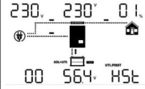 | 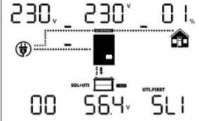 |
Step 5: If there is no more fault alarm, the parallel system is completely installed. 第 5 步:如果不再有故障报警,则并机系统已完全安装。
Step 6: Please switch on all breakers of Line wires in load side. This system will start to provide power to the load. 第 6 步:请打开负载侧 Line Wire 的所有断路器。该系统将开始为负载供电。
Parallel in Three Phase 三相并联
Step 1: Check the following requirements before commissioning: 第 1 步:调试前检查以下要求:
Correct wire connection 正确的电线连接
Ensure all breakers in Line wires of load side are open and each Neutral wires of each unit are connected together. 确保负载侧 Line Wire 中的所有断路器都打开,并且每个单元的每个零线都连接在一起。
Step 2: Turn on all units and configure LCD program 23 as P1, P2 and P3 sequentially. Then shut down all units. Note: It’s necessary to turn off switch when setting LCD program. Otherwise, the setting cannot be programmed. 第 2 步:打开所有单元,依次将 LCD 程序 23 配置为 P1、P2 和 P3。然后关闭所有设备。请注意: 设置 LCD 程序时需要关闭开关。否则,无法对设置进行编程。
Step 3: Turn on all units sequentially. Please turn on HOST inverter first, then turn on the rest one by one. 第 3 步:按顺序打开所有单元。请先打开 HOST 逆变器,然后逐个打开其余的。
Step 4: Switch on all AC breakers of Line wires in AC input. If AC connection is detected and three phases are matched with unit setting, they will work normally. Otherwise, theywill display warning 15/16 and will not work in the line mode. 第 4 步:打开交流输入中线路的所有交流断路器。如果检测到交流连接,并且三相与单位设置匹配,它们将正常工作。否则,它们将显示警告 15/16,并且在行模式下不起作用。
Step 5: If there is no more fault alarm, the system to support 3-phase equipment is completely installed. 第 5 步:如果不再有故障报警,则支持三相设备的系统已完全安装。
Step 6: Please switch on all breakers of Line wires in load side. This system will start to provide power to the load. 第 6 步:请打开负载侧 Line Wire 的所有断路器。该系统将开始为负载供电。
Note 1: If there’s only one inverter in L1-phase, the LCD will show as “HST”. If there is more than one inverter in L1-phase, the LCD of the HOST inverter will show as “HST”, the rest of L1-phase inverters will show as “3P1”. 注 1:如果 L1 相只有一个逆变器,LCD 将显示为“HST”。如果 L1 相有多个逆变器,HOST 逆变器的 LCD 将显示为“HST”,其余的 L1 相逆变器将显示为“3P1”。
Note 2: To avoid overload occurring, before turning on breakers in load side, it’s better to have whole system in operation first. 注 2:为避免过载发生,在负载侧接通断路器之前,最好先让整个系统运行。
Note 3: Transfer time for this operation exists. Power interruption may happen to critical devices, which cannot bear transfer time. 注 3:此作的传输时间存在。关键设备可能会发生电源中断,这些设备无法承受传输时间。
Note4: In a single-phase parallel system, when some inverters are connected to solar energy, energy can be obtained from the AC output end due to the parallel connection of the AC output end, resulting in energy transmission between inverters. Therefore, the AC input and AC output power displayed on the LCD display screen of a single inverter cannot accurately represent the energy flow of the inverter. It needs to be judged based on the total AC input and AC output power of the entire parallel system. (This phenomenon also exists between inverters in the same phase in a three-phase parallel system.) 注4:在单相并联系统中,当部分逆变器连接太阳能时,由于交流输出端并联,可以从交流输出端获得能量,从而在逆变器之间传输能量。因此,单个逆变器的液晶显示屏上显示的交流输入和交流输出功率并不能准确表示逆变器的能量流向。需要根据整个并联系统的总交流输入和交流输出功率来判断。(这种现象也存在于三相并联系统中同相的逆变器之间。
5.6 Example of a parallel system diagram 5.6 并行系统图示例
Single-phase parallel wire connection: 单相并联电线连接:
Three-phase parallel wire connection: 三相并联电线连接:
6.Fault Reference Code 6.故障参考代码
6.1 Fault Reference Code 6.1 故障参考代码
Fault Code 故障代码
Fault Event 故障事件
Icon on 图标
02
Over temperature 过温
03
Battery voltage is too high 电池电压过高
05
Output short circuited 输出短路
06
Output voltage is too high. 输出电压太高。
07
Overload time out 过载超时
08
Bus voltage is too high 总线电压过高
09
Bus soft start failed 总线软启动失败
11
The main relay failed 主继电器故障
12
The INV relay failed INV 中继失败
51
Over current or surge 过流或浪涌
52
Bus voltage is too low 总线电压过低
53
Inverter soft start failed 逆变器软启动失败
58
Output voltage is too low 输出电压太低
60
Negative power fault 负电源故障
61
PV voltage is too high PV 电压过高
62
Internal communication error 内部通信错误
65
BUS voltage imbalance BUS 电压不平衡
66
GFCI is too high GFCI 太高
67
DCI failed DCI 失败
70
Battery input overcurrent 电池输入过流
80
CAN fault CAN 故障
Fault Code Fault Event Icon on
02 Over temperature https://cdn.mathpix.com/cropped/2025_07_03_e5427370408cc080841fg-23.jpg?height=60&width=114&top_left_y=372&top_left_x=1029
03 Battery voltage is too high https://cdn.mathpix.com/cropped/2025_07_03_e5427370408cc080841fg-23.jpg?height=62&width=114&top_left_y=439&top_left_x=1029
05 Output short circuited https://cdn.mathpix.com/cropped/2025_07_03_e5427370408cc080841fg-23.jpg?height=61&width=110&top_left_y=506&top_left_x=1031
06 Output voltage is too high. https://cdn.mathpix.com/cropped/2025_07_03_e5427370408cc080841fg-23.jpg?height=60&width=108&top_left_y=573&top_left_x=1030
07 Overload time out https://cdn.mathpix.com/cropped/2025_07_03_e5427370408cc080841fg-23.jpg?height=62&width=108&top_left_y=638&top_left_x=1030
08 Bus voltage is too high https://cdn.mathpix.com/cropped/2025_07_03_e5427370408cc080841fg-23.jpg?height=58&width=106&top_left_y=710&top_left_x=1029
09 Bus soft start failed https://cdn.mathpix.com/cropped/2025_07_03_e5427370408cc080841fg-23.jpg?height=57&width=103&top_left_y=773&top_left_x=1031
11 The main relay failed https://cdn.mathpix.com/cropped/2025_07_03_e5427370408cc080841fg-23.jpg?height=50&width=82&top_left_y=854&top_left_x=1041
12 The INV relay failed https://cdn.mathpix.com/cropped/2025_07_03_e5427370408cc080841fg-23.jpg?height=66&width=103&top_left_y=905&top_left_x=1042
51 Over current or surge https://cdn.mathpix.com/cropped/2025_07_03_e5427370408cc080841fg-23.jpg?height=54&width=108&top_left_y=981&top_left_x=1030
52 Bus voltage is too low https://cdn.mathpix.com/cropped/2025_07_03_e5427370408cc080841fg-23.jpg?height=59&width=106&top_left_y=1041&top_left_x=1029
53 Inverter soft start failed https://cdn.mathpix.com/cropped/2025_07_03_e5427370408cc080841fg-23.jpg?height=59&width=108&top_left_y=1111&top_left_x=1030
58 Output voltage is too low https://cdn.mathpix.com/cropped/2025_07_03_e5427370408cc080841fg-23.jpg?height=54&width=108&top_left_y=1176&top_left_x=1030
60 Negative power fault https://cdn.mathpix.com/cropped/2025_07_03_e5427370408cc080841fg-23.jpg?height=58&width=108&top_left_y=1244&top_left_x=1032
61 PV voltage is too high https://cdn.mathpix.com/cropped/2025_07_03_e5427370408cc080841fg-23.jpg?height=53&width=106&top_left_y=1315&top_left_x=1033
62 Internal communication error https://cdn.mathpix.com/cropped/2025_07_03_e5427370408cc080841fg-23.jpg?height=58&width=106&top_left_y=1380&top_left_x=1029
65 BUS voltage imbalance https://cdn.mathpix.com/cropped/2025_07_03_e5427370408cc080841fg-23.jpg?height=58&width=106&top_left_y=1443&top_left_x=1029
66 GFCI is too high https://cdn.mathpix.com/cropped/2025_07_03_e5427370408cc080841fg-23.jpg?height=58&width=108&top_left_y=1509&top_left_x=1030
67 DCI failed https://cdn.mathpix.com/cropped/2025_07_03_e5427370408cc080841fg-23.jpg?height=58&width=108&top_left_y=1576&top_left_x=1030
70 Battery input overcurrent https://cdn.mathpix.com/cropped/2025_07_03_e5427370408cc080841fg-23.jpg?height=65&width=114&top_left_y=1642&top_left_x=1029
80 CAN fault https://cdn.mathpix.com/cropped/2025_07_03_e5427370408cc080841fg-23.jpg?height=56&width=108&top_left_y=1711&top_left_x=1030| Fault Code | Fault Event | Icon on |
| :--- | :--- | :--- |
| 02 | Over temperature |  |
| 03 | Battery voltage is too high |  |
| 05 | Output short circuited |  |
| 06 | Output voltage is too high. |  |
| 07 | Overload time out |  |
| 08 | Bus voltage is too high |  |
| 09 | Bus soft start failed |  |
| 11 | The main relay failed |  |
| 12 | The INV relay failed |  |
| 51 | Over current or surge |  |
| 52 | Bus voltage is too low |  |
| 53 | Inverter soft start failed |  |
| 58 | Output voltage is too low |  |
| 60 | Negative power fault |  |
| 61 | PV voltage is too high |  |
| 62 | Internal communication error |  |
| 65 | BUS voltage imbalance |  |
| 66 | GFCI is too high |  |
| 67 | DCI failed |  |
| 70 | Battery input overcurrent |  |
| 80 | CAN fault |  |
6.2 Warning Indicator 6.2 警告指示灯
Warning 警告
Warning Event 警告事件
Audible Alarm 声音警报
Icon flashing 图标闪烁
01
Fan is locked when inverter is on 逆变器开启时风扇被锁定
Beep 3 times every second 每秒发出 3 次哔哔声
02
Over temperature 过温
Beep once every second 每秒发出一次哔哔声
BE
03
Battery is over-charged 电池过度充电
Beep once every second 每秒发出一次哔哔声
nn EE/_\\cap \exists \triangle
04
Low battery 电池电量低
Beep once every second 每秒发出一次哔哔声
Q4
07
Overload 超载
Beep once every 0.5 second 每 0.5 秒发出一次哔哔声
nn◻/_\\cap \square \triangle
10
Output power derating voltage 输出功率降额电压
Beep twice every 3 seconds 每 3 秒发出两次哔哔声
1Omega/_\1 \Omega \triangle
13
Solar charger stops due to high PV voltage 太阳能充电器因高 PV 电压而停止
Beep once every second 每秒发出一次哔哔声
1EE/_\1 \exists \triangle
14
Solar charger stops due to overload 太阳能充电器因过载而停止
Beep once every second 每秒发出一次哔哔声
14-
15
Parallel input utility grid different 并行输入实用网格不同
Beep once every second 每秒发出一次哔哔声
15 (
16
Parallel input phase error 并联输入相位误差
Beep once every second 每秒发出一次哔哔声
岶内
17
Parallel output phase loss 并联输出相位损耗
Beep once every second 每秒发出一次哔哔声
17
18
BUS over current BUS over current (总线过电流)
Beep once every second 每秒发出一次哔哔声
19
Battery disconnect 电池断开
No beep 无蜂鸣声
19/_\19 \triangle
20
BMS communication error BMS 通信错误
Beep once every second 每秒发出一次哔哔声
ZO/_\\mathrm{ZO} \triangle
21
PV power insufficient 光伏功率不足
Beep once every second 每秒发出一次哔哔声
ℶ∣/_\\beth \mid \triangle
22
Parallel forbidden without battery 禁止无电池并联
Beep once every second 每秒发出一次哔哔声
Ze/_\\mathrm{Ze} \triangle
23
The parallel version is different 并行版本不同
Beep once every second 每秒发出一次哔哔声
コヨ』 红叶”
25
Parallel inverters'capacity different 并联逆变器的容量不同
Beep once every second 每秒发出一次哔哔声
25 Delta25 \Delta
26
ISO detection failed ISO 检测失败
Beep once every second 每秒发出一次哔哔声
26/_\26 \triangle
27
Abnormal grounding warning 异常接地警告
Beep once every second 每秒发出一次哔哔声
2~|/_\2\rceil \triangle
28
GFCI error GFCI 错误
Beep once every second 每秒发出一次哔哔声
28/_\28 \triangle
29
LLC overcurrent LLC 过电流
Beep once every second 每秒发出一次哔哔声
29/_\29 \triangle
30
BUS low voltage BUS 低电压
Beep once every second 每秒发出一次哔哔声
EE◻/_\\exists \square \triangle
31
In consistent switches 在一致的交换机中
Beep once every second 每秒发出一次哔哔声
EE1≜\exists 1 \triangleq
36
Total over voltage 总过电压
Beep once every second 每秒发出一次哔哔声
EE6^(/_\)\exists 6^{\triangle}
37
Total under voltage 总欠压
Beep once every second 每秒发出一次哔哔声
EE7/_\\exists 7 \triangle
38
Charge over voltage 充电过电压
Beep once every second 每秒发出一次哔哔声
39
Discharge over temperature 超温放电
Beep once every second 每秒发出一次哔哔声
EE9≜\exists 9 \triangleq
40
Discharge over temperature 超温放电
Beep once every second 每秒发出一次哔哔声
4◻/_\4 \square \triangle
41
Charge over temperature 随温度充电
Beep once every second 每秒发出一次哔哔声
41.4
81
Host loss 主机丢失
Beep once every second 每秒发出一次哔哔声
◻\square
Warning Warning Event Audible Alarm Icon flashing
01 Fan is locked when inverter is on Beep 3 times every second https://cdn.mathpix.com/cropped/2025_07_03_e5427370408cc080841fg-23.jpg?height=45&width=84&top_left_y=259&top_left_x=2474
02 Over temperature Beep once every second BE
03 Battery is over-charged Beep once every second nn EE/_\
04 Low battery Beep once every second Q4
07 Overload Beep once every 0.5 second nn◻/_\
10 Output power derating voltage Beep twice every 3 seconds 1Omega/_\
13 Solar charger stops due to high PV voltage Beep once every second 1EE/_\
14 Solar charger stops due to overload Beep once every second 14-
15 Parallel input utility grid different Beep once every second 15 (
16 Parallel input phase error Beep once every second 岶内
17 Parallel output phase loss Beep once every second 17
18 BUS over current Beep once every second https://cdn.mathpix.com/cropped/2025_07_03_e5427370408cc080841fg-23.jpg?height=43&width=65&top_left_y=835&top_left_x=2476
19 Battery disconnect No beep 19/_\
20 BMS communication error Beep once every second ZO/_\
21 PV power insufficient Beep once every second ℶ∣/_\
22 Parallel forbidden without battery Beep once every second Ze/_\
23 The parallel version is different Beep once every second コヨ』
25 Parallel inverters'capacity different Beep once every second 25 Delta
26 ISO detection failed Beep once every second 26/_\
27 Abnormal grounding warning Beep once every second 2~|/_\
28 GFCI error Beep once every second 28/_\
29 LLC overcurrent Beep once every second 29/_\
30 BUS low voltage Beep once every second EE◻/_\
31 In consistent switches Beep once every second EE1≜
36 Total over voltage Beep once every second EE6^(/_\)
37 Total under voltage Beep once every second EE7/_\
38 Charge over voltage Beep once every second https://cdn.mathpix.com/cropped/2025_07_03_e5427370408cc080841fg-23.jpg?height=44&width=78&top_left_y=1571&top_left_x=2477
39 Discharge over temperature Beep once every second EE9≜
40 Discharge over temperature Beep once every second 4◻/_\
41 Charge over temperature Beep once every second 41.4
81 Host loss Beep once every second ◻| Warning | Warning Event | Audible Alarm | Icon flashing |
| :--- | :--- | :--- | :--- |
| 01 | Fan is locked when inverter is on | Beep 3 times every second |  |
| 02 | Over temperature | Beep once every second | BE |
| 03 | Battery is over-charged | Beep once every second | $\cap \exists \triangle$ |
| 04 | Low battery | Beep once every second | Q4 |
| 07 | Overload | Beep once every 0.5 second | $\cap \square \triangle$ |
| 10 | Output power derating voltage | Beep twice every 3 seconds | $1 \Omega \triangle$ |
| 13 | Solar charger stops due to high PV voltage | Beep once every second | $1 \exists \triangle$ |
| 14 | Solar charger stops due to overload | Beep once every second | 14- |
| 15 | Parallel input utility grid different | Beep once every second | 15 ( |
| 16 | Parallel input phase error | Beep once every second | 岶内 |
| 17 | Parallel output phase loss | Beep once every second | 17 |
| 18 | BUS over current | Beep once every second |  |
| 19 | Battery disconnect | No beep | $19 \triangle$ |
| 20 | BMS communication error | Beep once every second | $\mathrm{ZO} \triangle$ |
| 21 | PV power insufficient | Beep once every second | $\beth \mid \triangle$ |
| 22 | Parallel forbidden without battery | Beep once every second | $\mathrm{Ze} \triangle$ |
| 23 | The parallel version is different | Beep once every second | コヨ』 |
| 25 | Parallel inverters'capacity different | Beep once every second | $25 \Delta$ |
| 26 | ISO detection failed | Beep once every second | $26 \triangle$ |
| 27 | Abnormal grounding warning | Beep once every second | $2\rceil \triangle$ |
| 28 | GFCI error | Beep once every second | $28 \triangle$ |
| 29 | LLC overcurrent | Beep once every second | $29 \triangle$ |
| 30 | BUS low voltage | Beep once every second | $\exists \square \triangle$ |
| 31 | In consistent switches | Beep once every second | $\exists 1 \triangleq$ |
| 36 | Total over voltage | Beep once every second | $\exists 6^{\triangle}$ |
| 37 | Total under voltage | Beep once every second | $\exists 7 \triangle$ |
| 38 | Charge over voltage | Beep once every second |  |
| 39 | Discharge over temperature | Beep once every second | $\exists 9 \triangleq$ |
| 40 | Discharge over temperature | Beep once every second | $4 \square \triangle$ |
| 41 | Charge over temperature | Beep once every second | 41.4 |
| 81 | Host loss | Beep once every second | $\square$ |
7. Specifications 7. 规格
7.1 PV Specification 7.1 光伏规格
It's applicable to Grid Tie & Hybrid & Off Grid 它适用于电网、平局、混合和离网
Max. short-circuit current per MPPT tracker 每个 MPPT 跟踪器的最大短路电流
34Amp 34安培
34Amp 34安培
34Amp 34安培
PV Voltage Accuracy PV 电压精度
+//-5V+/-5 \mathrm{~V}
It's applicable to Grid Tie & Hybrid & Off Grid
Model SPE 12000 ES SPE 10000 ES SPE 8000 ES
Max. power 15000 W 12500 W 10000 W
Max. PV Array Open Circuit Voltage 550 Vdc
Nominal PV Voltage 380 Vdc 380 Vdc 380 Vdc
Full load MPPT voltage rated 280Vdc∼480Vdc 240Vdc∼480Vdc 190Vdc∼480Vdc
PV Start-up Voltage 120Vdc+-10V
PV Array Voltage High Loss 550 Vdc
PV Array Voltage High Comeback 520 Vdc
PV Array Voltage Low Loss 60 Vdc
PV Array Voltage Low Back 120 Vdc
PV MPPT Voltage Range 60Vdc∼480Vdc
PV MPPT Voltage Low Loss 60 Vdc
PV MPPT Voltage Low Back 75 Vdc
Number of MPP Trackers 2
Max. DC Input current per string 27Amp 27Amp 27Amp
Max. short-circuit current per MPPT tracker 34Amp 34Amp 34Amp
PV Voltage Accuracy +//-5V | It's applicable to Grid Tie & Hybrid & Off Grid | | | |
| :--- | :--- | :--- | :--- |
| Model | SPE 12000 ES | SPE 10000 ES | SPE 8000 ES |
| Max. power | 15000 W | 12500 W | 10000 W |
| Max. PV Array Open Circuit Voltage | 550 Vdc | | |
| Nominal PV Voltage | 380 Vdc | 380 Vdc | 380 Vdc |
| Full load MPPT voltage rated | $280 \mathrm{Vdc} \sim 480 \mathrm{Vdc}$ | $240 \mathrm{Vdc} \sim 480 \mathrm{Vdc}$ | $190 \mathrm{Vdc} \sim 480 \mathrm{Vdc}$ |
| PV Start-up Voltage | $120 \mathrm{Vdc} \pm 10 \mathrm{~V}$ | | |
| PV Array Voltage High Loss | 550 Vdc | | |
| PV Array Voltage High Comeback | 520 Vdc | | |
| PV Array Voltage Low Loss | 60 Vdc | | |
| PV Array Voltage Low Back | 120 Vdc | | |
| PV MPPT Voltage Range | $60 \mathrm{Vdc} \sim 480 \mathrm{Vdc}$ | | |
| PV MPPT Voltage Low Loss | 60 Vdc | | |
| PV MPPT Voltage Low Back | 75 Vdc | | |
| Number of MPP Trackers | 2 | | |
| Max. DC Input current per string | 27Amp | 27Amp | 27Amp |
| Max. short-circuit current per MPPT tracker | 34Amp | 34Amp | 34Amp |
| PV Voltage Accuracy | $+/-5 \mathrm{~V}$ | | |
70Amp (Include Loads and Charging) 70Amp (包括负载和充电)
Rating of Transfer Relay 传输继电器的评级
70Amp (Include Loads and Charging) 70Amp (包括负载和充电)
It's applicable to Hybrid & Off-Grid
Model SPE 12000 ES SPE 10000 ES SPE 8000 ES
Nominal Input Voltage 230 Vac
Low Loss Voltage 170Vac+-7V(UPS);90Vac+-7V (Appliances)
Low Loss Return Voltage 180Vac+-7V (UPS); 100Vac+-7V (Appliances)
High Loss Voltage 280Vac+-7V
High Loss Return Voltage 270Vac+-7V
Max AC Input Voltage 300 Vac
Nominal Input Frequency 50Hz//60Hz (Auto detection)
AC input frequency range 40.0∼65.0Hz
AC input frequency comeback value 42.0//63.0Hz
Max. AC Input current 70Amp (Include Loads and Charging)
Rating of Transfer Relay 70Amp (Include Loads and Charging) | It's applicable to Hybrid & Off-Grid | | | |
| :--- | :--- | :--- | :--- |
| Model | SPE 12000 ES | SPE 10000 ES | SPE 8000 ES |
| Nominal Input Voltage | 230 Vac | | |
| Low Loss Voltage | $170 \mathrm{Vac} \pm 7 \mathrm{~V}(\mathrm{UPS}) ; 90 \mathrm{Vac} \pm 7 \mathrm{~V}$ (Appliances) | | |
| Low Loss Return Voltage | $180 \mathrm{Vac} \pm 7 \mathrm{~V}$ (UPS); $100 \mathrm{Vac} \pm 7 \mathrm{~V}$ (Appliances) | | |
| High Loss Voltage | $280 \mathrm{Vac} \pm 7 \mathrm{~V}$ | | |
| High Loss Return Voltage | $270 \mathrm{Vac} \pm 7 \mathrm{~V}$ | | |
| Max AC Input Voltage | 300 Vac | | |
| Nominal Input Frequency | $50 \mathrm{~Hz} / 60 \mathrm{~Hz}$ (Auto detection) | | |
| AC input frequency range | $40.0 \sim 65.0 \mathrm{~Hz}$ | | |
| AC input frequency comeback value | $42.0 / 63.0 \mathrm{~Hz}$ | | |
| Max. AC Input current | 70Amp (Include Loads and Charging) | | |
| Rating of Transfer Relay | 70Amp (Include Loads and Charging) | | |
7.3 Grid Feeding Specification 7.3 网格进料规格
It's applicable to Grid-tie & Hybrid 它适用于 Grid-tie 和 Hybrid
<3% for linear load, <5% for non-linear load @ V nominal 线性负载为 <3%,非线性负载 @ V 标称值为 <5%
Output DC offset 输出 DC 偏移
< 150mV<150 \mathrm{mV}
Peak Efficiency 峰值效率
95%
No Load Power Consumption 空载功耗
<75W@Rate Voltage
Transfer Time 转移时间
< 20ms@<20 \mathrm{~ms} @ Single < 30ms<30 \mathrm{~ms} @ Parallel < 20ms@<20 \mathrm{~ms} @ Single < 30ms<30 \mathrm{~ms} @ 并行
Output Parallel-able 输出可并联
Yes 是的
Model SPE 12000 ES SPE 10000 ES SPE 8000 ES
Nominal Output Power 12000 W 10000 W 8000 W
Max Discharge Current 280A 240A 200A
Waveform Pure Sine Wave
Nominal Output Voltage 230 Vac
Nominal Output Frequency 50//60Hz auto sensing
Output Voltage Distortion <3% for linear load, <5% for non-linear load @ V nominal
Output DC offset < 150mV
Peak Efficiency 95%
No Load Power Consumption <75W@Rate Voltage
Transfer Time < 20ms@ Single < 30ms @ Parallel
Output Parallel-able Yes | Model | SPE 12000 ES | SPE 10000 ES | SPE 8000 ES |
| :--- | :--- | :--- | :--- |
| Nominal Output Power | 12000 W | 10000 W | 8000 W |
| Max Discharge Current | 280A | 240A | 200A |
| Waveform | Pure Sine Wave | | |
| Nominal Output Voltage | 230 Vac | | |
| Nominal Output Frequency | $50 / 60 \mathrm{~Hz}$ auto sensing | | |
| Output Voltage Distortion | <3% for linear load, <5% for non-linear load @ V nominal | | |
| Output DC offset | $<150 \mathrm{mV}$ | | |
| Peak Efficiency | 95% | | |
| No Load Power Consumption | <75W@Rate Voltage | | |
| Transfer Time | $<20 \mathrm{~ms} @$ Single $<30 \mathrm{~ms}$ @ Parallel | | |
| Output Parallel-able | Yes | | |
7.5 Smart Load Output Power Specification 7.5 智能负载输出功率规格
Model 型
SPE 12000 ES 单精度仪 12000 ES
SPE 10000 ES
SPE 8000 ES
Full Load Output Power 满载输出功率
12000 W 12000 瓦
10000 W 10000 瓦
8000 W 8000 瓦
Maximum Main Load 最大主载荷
12000 W 12000 瓦
10000 W 10000 瓦
8000 W 8000 瓦
Maximum smart load 最大智能负载
8000 W 8000 瓦
8000 W 8000 瓦
8000 W 8000 瓦
Model SPE 12000 ES SPE 10000 ES SPE 8000 ES
Full Load Output Power 12000 W 10000 W 8000 W
Maximum Main Load 12000 W 10000 W 8000 W
Maximum smart load 8000 W 8000 W 8000 W| Model | SPE 12000 ES | SPE 10000 ES | SPE 8000 ES |
| :--- | :---: | :---: | :---: |
| Full Load Output Power | 12000 W | 10000 W | 8000 W |
| Maximum Main Load | 12000 W | 10000 W | 8000 W |
| Maximum smart load | 8000 W | 8000 W | 8000 W |
7.6 Overload Capability Specification 7.6 过载能力规格
Line Mode
@ > 70A>70 \mathrm{~A} AC input current, 1 min @ > 70A>70 \mathrm{~A} 交流输入电流,1 分钟
Battery Mode 电池模式
5sec, @>120% Load 5 秒,@>120% 负载
10sec, @103%~120% 10 秒,@103%~120%
4-cycle, short-circuits 4 周期,短路
Line Mode @ > 70A AC input current, 1 min
Battery Mode 5sec, @>120% Load
10sec, @103%~120%
4-cycle, short-circuits| Line Mode | @ $>70 \mathrm{~A}$ AC input current, 1 min |
| :--- | :--- |
| Battery Mode | 5sec, @>120% Load |
| | 10sec, @103%~120% |
| | 4-cycle, short-circuits |
Model SPE 12000 ES SPE 10000 ES SPE 8000 ES
Operation Temperature Range -10^(@)C∼50^(@)C
Storage Temperature Range -15^(@)C∼60^(@)C
Altitude < 2000m
Relative humidity 5% ~ 95% non-condensing
Audible Noise < 75dB
Cooling DC FAN
Safety Certification CE | Model | SPE 12000 ES | SPE 10000 ES | SPE 8000 ES |
| :--- | :--- | :--- | :--- |
| Operation Temperature Range | $-10^{\circ} \mathrm{C} \sim 50^{\circ} \mathrm{C}$ | | |
| Storage Temperature Range | $-15^{\circ} \mathrm{C} \sim 60^{\circ} \mathrm{C}$ | | |
| Altitude | $<2000 \mathrm{~m}$ | | |
| Relative humidity | 5% ~ 95% non-condensing | | |
| Audible Noise | $<75 \mathrm{~dB}$ | | |
| Cooling | DC FAN | | |
| Safety Certification | CE | | |
7.9 Mechanical Specification 7.9 机械规格
Model 型
SPE 12000 ES 单精度仪 12000 ES
SPE 10000 ES
SPE 8000 ES
Housing Dimension (LWH), mm 外壳尺寸(长 、宽 、高)、mm
550465150 mm 550465150 毫米
Packing Dimension (LWH), mm 包装尺寸(长宽高), 毫米
705625260 mm 705625260 毫米
Housing Color 外壳颜色
White 白
Net Weight, kg 净重,kg
21.5
Gross Weight, kg 毛重,kg
25.5
Model SPE 12000 ES SPE 10000 ES SPE 8000 ES
Housing Dimension (LWH), mm 550465150 mm
Packing Dimension (LWH), mm 705625260 mm
Housing Color White
Net Weight, kg 21.5
Gross Weight, kg 25.5 | Model | SPE 12000 ES | SPE 10000 ES | SPE 8000 ES |
| :--- | :--- | :--- | :--- |
| Housing Dimension (L*W*H), mm | 550*465*150 mm | | |
| Packing Dimension (L*W*H), mm | 705*625*260 mm | | |
| Housing Color | White | | |
| Net Weight, kg | 21.5 | | |
| Gross Weight, kg | 25.5 | | |
8. Appendix 8. 附录
Appendix I. Fault information and processing 附录一 故障信息及处理
The energy storage inverter is designed according to the off-grid connected operation standard and meets the safety requirements and electromagnetic compatibility requirements. Before leaving the factory, the inverter undergoes several rigorous tests to ensure that the inverter can operate reliably. 储能逆变器根据离网并网运行标准设计,满足安全要求和电磁兼容要求。在出厂前,逆变器经过了几次严格的测试,以确保逆变器能够可靠运行。
If any of the fault messages listed in Table 6-1 appear on your inverter and the fault has not been removed after restarting, please contact your local dealer or service center. You need to have the following information ready. 如果您的逆变器上出现表 6-1 中列出的任何故障信息,并且重新启动后故障仍未消除,请联系您当地的经销商或服务中心。您需要准备好以下信息。
Inverter serial number; 逆变器序列号;
The problem description (including the fault code and indicator status displayed on the LCD, or specific fault video and picture) is as detailed as possible. 问题描述(包括 LCD 上显示的故障代码和指示灯状态,或具体的故障视频和图片)尽可能详细。
Basic system component information (such as batteries, photovoltaic panels, load usage and specifications) 基本系统组件信息(例如电池、光伏板、负载使用情况和规格)
Your contact information. 您的联系信息。
In order to give you a clearer understanding of the inverter’s fault information, we will list all possible fault codes and their descriptions when the inverter is not working properly 为了让您更清楚地了解逆变器的故障信息,我们将列出逆变器无法正常工作时所有可能的故障代码及其描述
error code 错误代码
Description 描述
Solutions 解决 方案
F01
Fan is locked 风扇已锁定
1.检查所有风扇是否正常工作。 2. 更换风扇。
1.Check whether all fans are working properly.
2. Replace the fan.
1.Check whether all fans are working properly.
2. Replace the fan.| 1.Check whether all fans are working properly. |
| :--- |
| 2. Replace the fan. |
F02
Internal temperature of component is over 100^(@)C100^{\circ} \mathrm{C}. 组件内部温度超过 100^(@)C100^{\circ} \mathrm{C} 。
Check whether the air flow of the unit is blocked or whether the ambient temperature is too high. 检查机组气流是否堵塞或环境温度是否过高。
F03
Battery is over-charged. 电池过度充电。
Restart the unit 重新启动设备
The battery voltage is too high 电池电压过高
1.测量直流输入中的电池电压。(使用锂电池时检查 LCD 中的电池 SOC) 2.将充电电流调整到 0.2 C 以下 3.检查电池的规格和数量是否符合要求。
1.Measure battery voltage in DC input. (Check battery SOC in LCD when use Li battery)
2.Adjust the charging current to less than 0.2 C
3.Check if spec and quantity of batteries are meet requirements.
1.Measure battery voltage in DC input. (Check battery SOC in LCD when use Li battery)
2.Adjust the charging current to less than 0.2 C
3.Check if spec and quantity of batteries are meet requirements.| 1.Measure battery voltage in DC input. (Check battery SOC in LCD when use Li battery) |
| :--- |
| 2.Adjust the charging current to less than 0.2 C |
| 3.Check if spec and quantity of batteries are meet requirements. |
W04
Battery voltage is too low 电池电压过低
1.测量直流输入中的电池电压。(使用锂电池时检查 LCD 中的电池 SOC) 2. 给电池充电。
1.Measure battery voltage in DC input. (Check battery SOC in LCD when use Li battery)
2. Recharge the battery.
1.Measure battery voltage in DC input. (Check battery SOC in LCD when use Li battery)
2. Recharge the battery.| 1.Measure battery voltage in DC input. (Check battery SOC in LCD when use Li battery) |
| :--- |
| 2. Recharge the battery. |
F05
Output short circuited 输出短路
1.断开负载并重新启动设备 2.检查接线是否连接良好,并移除异常负载。
1.Disconnect load and restart the unit
2. Check if wiring is connected well and remove abnormal load.
1.Disconnect load and restart the unit
2. Check if wiring is connected well and remove abnormal load.| 1.Disconnect load and restart the unit |
| :--- |
| 2. Check if wiring is connected well and remove abnormal load. |
F07
Overload time out 过载超时
Reduce the connected load by switching off some equipment. 通过关闭一些设备来减少连接的负载。
F08
Bus voltage is too high 总线电压过高
1、如果连接锂电池没有通讯,请检查程序19和21的电压点是否对锂电池来说太高。 2. 重新启动设备
1. If you connect to a lithium battery without communication, check whether the voltage points of the program 19 and 21 are too high for the lithium battery.
2. Restart the unit
1. If you connect to a lithium battery without communication, check whether the voltage points of the program 19 and 21 are too high for the lithium battery.
2. Restart the unit| 1. If you connect to a lithium battery without communication, check whether the voltage points of the program 19 and 21 are too high for the lithium battery. |
| :--- |
| 2. Restart the unit |
F11/F12
Relay detection failed 中继检测失败
Restart the unit 重新启动设备
F09/F53/F57
Bus soft start failed 总线软启动失败
Restart the unit 重新启动设备
W15
The input status is different in parallel system. 并联系统中的输入状态不同。
Check if AC input wires of all inverters are connected well. 检查所有逆变器的交流输入线是否连接良好。
W16
Input phase is not correct. 输入相位不正确。
Change the input phase SS and TT wiring. 更改输入相位 SS 和 TT 接线。
W17
The output phase not correct in parallel. 输出相位并联不正确。
1.确保并行设置为同一系统(单或并行;3P1、3P2、3P3)。 2.确保所有相逆变器都已通电。
1.Make sure the parallel setting is the same System (single or parallel; 3P1,3P2,3P3).
2.Make sure all phases inverters are power on.
1.Make sure the parallel setting is the same System (single or parallel; 3P1,3P2,3P3).
2.Make sure all phases inverters are power on.| 1.Make sure the parallel setting is the same System (single or parallel; 3P1,3P2,3P3). |
| :--- |
| 2.Make sure all phases inverters are power on. |
W19
lead acid battery disconnect 铅酸电池断开连接
Check if spec and quantity of batteries are meet requirements. 检查电池的规格和数量是否满足要求。
error code Description Solutions
F01 Fan is locked "1.Check whether all fans are working properly.
2. Replace the fan."
F02 Internal temperature of component is over 100^(@)C. Check whether the air flow of the unit is blocked or whether the ambient temperature is too high.
F03 Battery is over-charged. Restart the unit
The battery voltage is too high "1.Measure battery voltage in DC input. (Check battery SOC in LCD when use Li battery)
2.Adjust the charging current to less than 0.2 C
3.Check if spec and quantity of batteries are meet requirements."
W04 Battery voltage is too low "1.Measure battery voltage in DC input. (Check battery SOC in LCD when use Li battery)
2. Recharge the battery."
F05 Output short circuited "1.Disconnect load and restart the unit
2. Check if wiring is connected well and remove abnormal load."
F07 Overload time out Reduce the connected load by switching off some equipment.
F08 Bus voltage is too high "1. If you connect to a lithium battery without communication, check whether the voltage points of the program 19 and 21 are too high for the lithium battery.
2. Restart the unit"
F11/F12 Relay detection failed Restart the unit
F09/F53/F57 Bus soft start failed Restart the unit
W15 The input status is different in parallel system. Check if AC input wires of all inverters are connected well.
W16 Input phase is not correct. Change the input phase S and T wiring.
W17 The output phase not correct in parallel. "1.Make sure the parallel setting is the same System (single or parallel; 3P1,3P2,3P3).
2.Make sure all phases inverters are power on."
W19 lead acid battery disconnect Check if spec and quantity of batteries are meet requirements.
Lithium battery disconnect "1. Check BMS communication cable connection
2. Check setup parameters"| error code | Description | Solutions |
| :--- | :--- | :--- |
| F01 | Fan is locked | 1.Check whether all fans are working properly. <br> 2. Replace the fan. |
| F02 | Internal temperature of component is over $100^{\circ} \mathrm{C}$. | Check whether the air flow of the unit is blocked or whether the ambient temperature is too high. |
| F03 | Battery is over-charged. | Restart the unit |
| | The battery voltage is too high | 1.Measure battery voltage in DC input. (Check battery SOC in LCD when use Li battery) <br> 2.Adjust the charging current to less than 0.2 C <br> 3.Check if spec and quantity of batteries are meet requirements. |
| W04 | Battery voltage is too low | 1.Measure battery voltage in DC input. (Check battery SOC in LCD when use Li battery) <br> 2. Recharge the battery. |
| F05 | Output short circuited | 1.Disconnect load and restart the unit <br> 2. Check if wiring is connected well and remove abnormal load. |
| F07 | Overload time out | Reduce the connected load by switching off some equipment. |
| F08 | Bus voltage is too high | 1. If you connect to a lithium battery without communication, check whether the voltage points of the program 19 and 21 are too high for the lithium battery. <br> 2. Restart the unit |
| F11/F12 | Relay detection failed | Restart the unit |
| F09/F53/F57 | Bus soft start failed | Restart the unit |
| W15 | The input status is different in parallel system. | Check if AC input wires of all inverters are connected well. |
| W16 | Input phase is not correct. | Change the input phase $S$ and $T$ wiring. |
| W17 | The output phase not correct in parallel. | 1.Make sure the parallel setting is the same System (single or parallel; 3P1,3P2,3P3). <br> 2.Make sure all phases inverters are power on. |
| W19 | lead acid battery disconnect | Check if spec and quantity of batteries are meet requirements. |
| | Lithium battery disconnect | 1. Check BMS communication cable connection <br> 2. Check setup parameters |
W20
BMS communication error BMS 通信错误
1. Check whether communication line is correct connection between inverter and battery. 2. Check whether BMS protocol type is correct setting. 1. 检查逆变器和电池之间的通讯线是否连接正确。2. 检查 BMS 协议类型设置是否正确。
W27
Abnormal grounding warning 异常接地警告
Check whether the ground connection is normal. 检查接地是否正常。
W31
Inconsistent switches 不一致的交换机
Check if all inverter switches are closed 检查所有逆变器开关是否合闸
F29/F51 F29/F51 系列
Over current or surge 过流或浪涌
Restart the unit 重新启动设备
F52
Bus voltage is too low 总线电压过低
Restart the unit 重新启动设备
F55
Output voltage is unbalanced 输出电压不平衡
Restart the unit 重新启动设备
F61
PV voltage is too high PV 电压过高
1. Measure whether the PV voltage in the DC input is consistent with the value displayed on the LCD screen. 2. If consistent, standardize the parallel connection method of PV panels. 1. 测量直流输入中的 PV 电压是否与 LCD 屏幕上显示的值一致。2. 如果一致,规范光伏板的并联方法。
F62
Internal communication error 内部通信错误
Restart the unit 重新启动设备
F65
BUS voltage imbalance BUS 电压不平衡
Restart the unit 重新启动设备
F66
GFCI is too high GFCI 太高
1.Check if the load equipment has a leakage phenomenon 2. Restart the unit 1.检查负载设备是否有漏电现象 2.重新启动设备
F67
DCI failed DCI 失败
Restart the unit 重新启动设备
F70
Battery input overcurrent 电池输入过流
Reduce the connected load by switching off some equipment. 通过关闭一些设备来减少连接的负载。
F80
CAN fault CAN 故障
F81
Host loss 主机丢失
1. Check whether the parallel communication cables are connected well. 1. 检查并联通信电缆是否连接良好。
W20 BMS communication error 1. Check whether communication line is correct connection between inverter and battery. 2. Check whether BMS protocol type is correct setting.
W27 Abnormal grounding warning Check whether the ground connection is normal.
W31 Inconsistent switches Check if all inverter switches are closed
F29/F51 Over current or surge Restart the unit
F52 Bus voltage is too low Restart the unit
F55 Output voltage is unbalanced Restart the unit
F61 PV voltage is too high 1. Measure whether the PV voltage in the DC input is consistent with the value displayed on the LCD screen. 2. If consistent, standardize the parallel connection method of PV panels.
F62 Internal communication error Restart the unit
F65 BUS voltage imbalance Restart the unit
F66 GFCI is too high 1.Check if the load equipment has a leakage phenomenon 2. Restart the unit
F67 DCI failed Restart the unit
F70 Battery input overcurrent Reduce the connected load by switching off some equipment.
F80 CAN fault
F81 Host loss 1. Check whether the parallel communication cables are connected well.| W20 | BMS communication error | 1. Check whether communication line is correct connection between inverter and battery. 2. Check whether BMS protocol type is correct setting. |
| :--- | :--- | :--- |
| W27 | Abnormal grounding warning | Check whether the ground connection is normal. |
| W31 | Inconsistent switches | Check if all inverter switches are closed |
| F29/F51 | Over current or surge | Restart the unit |
| F52 | Bus voltage is too low | Restart the unit |
| F55 | Output voltage is unbalanced | Restart the unit |
| F61 | PV voltage is too high | 1. Measure whether the PV voltage in the DC input is consistent with the value displayed on the LCD screen. 2. If consistent, standardize the parallel connection method of PV panels. |
| F62 | Internal communication error | Restart the unit |
| F65 | BUS voltage imbalance | Restart the unit |
| F66 | GFCI is too high | 1.Check if the load equipment has a leakage phenomenon 2. Restart the unit |
| F67 | DCI failed | Restart the unit |
| F70 | Battery input overcurrent | Reduce the connected load by switching off some equipment. |
| F80 | CAN fault | |
| F81 | Host loss | 1. Check whether the parallel communication cables are connected well. |
Other Problem 其他问题
LCD/LED/Buzzer LCD/LED/蜂鸣器
Explanation 解释
What to do 该怎么做
Unit shuts down Automatically during startup process. 设备在启动过程中自动关闭。
LCD/LEDs and buzzer will be active for 3 seconds and then complete off. LCD/LED 和蜂鸣器将激活 3 秒钟,然后完全关闭。
The battery voltage is too low. (<1.91V/Cell) 电池电压过低。(<1.91V/节)
1. The battery voltage is far too low. (<1.4V/Cell)
2.Battery polarity is connected reversed.
1. The battery voltage is far too low. (<1.4V/Cell)
2.Battery polarity is connected reversed.| 1. The battery voltage is far too low. (<1.4V/Cell) |
| :--- |
| 2.Battery polarity is connected reversed. |
1.检查电池和接线是否连接良好。 2.给电池充电。 3.更换电池。
1.Check if batteries and the wiring are connected well.
2.Re-charge battery.
3.Replace battery.
1.Check if batteries and the wiring are connected well.
2.Re-charge battery.
3.Replace battery.| 1.Check if batteries and the wiring are connected well. |
| :--- |
| 2.Re-charge battery. |
| 3.Replace battery. |
Mains exist butthe unit works in battery mode. 市电存在,但设备在电池模式下工作。
Input voltage is 0 on the LCD and green LED is flashing. LCD 上的输入电压为 0,绿色 LED 闪烁。
Input protector is tripped. 输入保护器跳闸。
Check if AC breaker is tripped and AC wiring is connected well. 检查交流断路器是否跳闸,交流电线是否连接良好。
Green LED is flashing. 绿色 LED 指示灯闪烁。
Insufficient quality of AC power (Shore or Generator) 交流电源质量不足(岸电或发电机)
2.Check if generator (if applied) is working well or if input voltage range setting is correct. (UPS rarr\rightarrow Appliance)
1.Check if AC wires are too thin and/or too long.
2.Check if generator (if applied) is working well or if input voltage range setting is correct. (UPS rarr Appliance)| 1.Check if AC wires are too thin and/or too long. |
| :--- |
| 2.Check if generator (if applied) is working well or if input voltage range setting is correct. (UPS $\rightarrow$ Appliance) |
Green LED is flashing. 绿色 LED 指示灯闪烁。
Set "Battery First" or "Solar First" as the priority of output source. 将 “Battery First” 或 “Solar First” 设置为输出源的优先级。
Change output source priority to Utility first. 首先将输出源优先级更改为 Utility。
When it's turned on,internal relay is switching on and off repeatedly. 当它打开时,内部继电器会反复打开和关闭。
LCD display and LEDs are flashing LCD 显示屏和 LED 指示灯闪烁
Battery is disconnected. 电池已断开连接。
Check if battery wires are connected well. 检查电池线是否连接良好。
Other Problem LCD/LED/Buzzer Explanation What to do
Unit shuts down Automatically during startup process. LCD/LEDs and buzzer will be active for 3 seconds and then complete off. The battery voltage is too low. (<1.91V/Cell) "1. Re-charge battery.
2. Replace battery."
No response after power on. No indication. "1. The battery voltage is far too low. (<1.4V/Cell)
2.Battery polarity is connected reversed." "1.Check if batteries and the wiring are connected well.
2.Re-charge battery.
3.Replace battery."
Mains exist butthe unit works in battery mode. Input voltage is 0 on the LCD and green LED is flashing. Input protector is tripped. Check if AC breaker is tripped and AC wiring is connected well.
Green LED is flashing. Insufficient quality of AC power (Shore or Generator) "1.Check if AC wires are too thin and/or too long.
2.Check if generator (if applied) is working well or if input voltage range setting is correct. (UPS rarr Appliance)"
Green LED is flashing. Set "Battery First" or "Solar First" as the priority of output source. Change output source priority to Utility first.
When it's turned on,internal relay is switching on and off repeatedly. LCD display and LEDs are flashing Battery is disconnected. Check if battery wires are connected well.| Other Problem | LCD/LED/Buzzer | Explanation | What to do |
| :--- | :--- | :--- | :--- |
| Unit shuts down Automatically during startup process. | LCD/LEDs and buzzer will be active for 3 seconds and then complete off. | The battery voltage is too low. (<1.91V/Cell) | 1. Re-charge battery. <br> 2. Replace battery. |
| No response after power on. | No indication. | 1. The battery voltage is far too low. (<1.4V/Cell) <br> 2.Battery polarity is connected reversed. | 1.Check if batteries and the wiring are connected well. <br> 2.Re-charge battery. <br> 3.Replace battery. |
| Mains exist butthe unit works in battery mode. | Input voltage is 0 on the LCD and green LED is flashing. | Input protector is tripped. | Check if AC breaker is tripped and AC wiring is connected well. |
| | Green LED is flashing. | Insufficient quality of AC power (Shore or Generator) | 1.Check if AC wires are too thin and/or too long. <br> 2.Check if generator (if applied) is working well or if input voltage range setting is correct. (UPS $\rightarrow$ Appliance) |
| | Green LED is flashing. | Set "Battery First" or "Solar First" as the priority of output source. | Change output source priority to Utility first. |
| When it's turned on,internal relay is switching on and off repeatedly. | LCD display and LEDs are flashing | Battery is disconnected. | Check if battery wires are connected well. |
Note: To restart the inverter, all power sources need to be disconnected. After the LCD screen light is off, only use the battery to boot. 请注意: 要重新启动逆变器,需要断开所有电源。LCD 屏幕指示灯熄灭后,只能使用电池启动。
Appendix II Restore factory settings 附录 II 恢复出厂设置
After pressing and holding UP and DOWN buttons at the same time for 3 seconds, the unit will enter PASS mode. Change the middle three numbers 000 to 305 . Press the “ENTER” button twice to confirm the selection, then press “ESC” to return and complete the settings. 同时按住 UP 和 DOWN 按钮 3 秒钟后,本机将进入 PASS 模式。将中间的三个数字 000 更改为 305 。按两次 “ENTER” 按钮确认选择,然后按 “ESC” 返回并完成设置。
If equalization function is enabled in program 43, this program can be setup. If "On" is selected in this program, it's to activate battery equalization immediately and LCD main page will shows " E ". If "Off" is selected, it will cancel equalization function until next activated equalization time arrives based on program 47setting. At this time, "Eq" will not be shown in LCD main page. 如果在程序 43 中启用了均衡功能,则可以设置该程序。如果在此程序中选择“开”,则立即激活电池均衡,LCD 主页将显示“E”。如果选择 “Off” ,它将取消均衡功能,直到根据程序 47 设置到下一个激活的均衡时间到来。此时,LCD 主页上不会显示 “Eq”。
43 Battery equalization Battery equalization enable Battery equalization disable(default) Eq di 5 , 04 곡
If "Flooded" or "User-Defined" is selected in program 05, this program can be set up.
44 Battery equalization voltage Default 58.4 V , 48.0V∼58.4V Settable
45 Battery equalized time is uarr
46 Battery equalized timeout https://cdn.mathpix.com/cropped/2025_07_03_e5427370408cc080841fg-27.jpg?height=202&width=346&top_left_y=1067&top_left_x=551 Default 120min,5min∼900min Settable
47 Equalization interval dRy Default 30days, 1 days~90 days Settable
48 Equalization activated immediately Equalization activated immediately on "Equalization activated immediately off(default)
Eq DFF 04:"
If equalization function is enabled in program 43, this program can be setup. If "On" is selected in this program, it's to activate battery equalization immediately and LCD main page will shows " E ". If "Off" is selected, it will cancel equalization function until next activated equalization time arrives based on program 47setting. At this time, "Eq" will not be shown in LCD main page. | 43 | Battery equalization | Battery equalization enable | Battery equalization disable(default) Eq di 5 , 04 곡 |
| :--- | :--- | :--- | :--- |
| | | If "Flooded" or "User-Defined" is selected in program 05, this program can be set up. | |
| 44 | Battery equalization voltage | Default 58.4 V , $48.0 \mathrm{~V} \sim 58.4 \mathrm{~V}$ Settable | |
| 45 | Battery equalized time | is $\uparrow$ | |
| 46 | Battery equalized timeout | 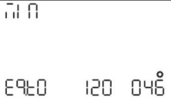 | Default $120 \mathrm{~min}, 5 \mathrm{~min} \sim 900 \mathrm{~min}$ Settable |
| 47 | Equalization interval | dRy | Default 30days, 1 days~90 days Settable |
| 48 | Equalization activated immediately | Equalization activated immediately on | Equalization activated immediately off(default) <br> Eq DFF 04: |
| | | If equalization function is enabled in program 43, this program can be setup. If "On" is selected in this program, it's to activate battery equalization immediately and LCD main page will shows " E ". If "Off" is selected, it will cancel equalization function until next activated equalization time arrives based on program 47setting. At this time, "Eq" will not be shown in LCD main page. | |
Equalization function is added into charge controller. It reverses the buildup of negative chemical effects like stratification, a condition where acid concentration is greater at the bottom of the battery than at the top. Equalization also helps to remove sulfate crystals that might have built up on the plates. If left unchecked, this condition, called sulfation, will reduce the overall capacity of the battery. Therefore, it’s recommended to equalize battery periodically. 在电荷控制器中增加了均衡功能。它逆转了负面化学效应的积累,例如分层,分层是电池底部的酸浓度高于顶部的情况。均衡还有助于去除可能堆积在板上的硫酸盐晶体。如果不加以控制,这种情况称为硫酸盐化,将降低电池的整体容量。因此,建议定期均衡电池。
How to Apply Equalization Function 如何应用均衡功能
You must enable battery equalization function in monitoring LCD setting program 43 first. Then, you may apply this function in device by either one of following methods: 您必须先在监控 LCD 设置程序 43 中启用电池均衡功能。然后,您可以通过以下任一方法在设备中应用此功能:
Setting equalization interval in program 47. 在程序 47 中设置均衡间隔。
Active equalization immediately in program 48. 立即在程序 48 中进行主动均衡。
When to Equalize 何时均衡
In float stage, when the setting equalization interval (battery equalization cycle) is arrived, or equalization is active immediately, the controller will start to enter Equalize stage. 在浮动阶段,当达到设置均衡间隔(电池均衡周期)或均衡立即激活时,控制器将开始进入均衡阶段。
Equalize charging time and timeout 均衡充电时间和超时
In Equalize stage, the controller will supply power to charge battery as much as possible until battery voltage raises to battery equalization voltage. Then, constant-voltage regulation is applied to maintain battery voltage at the battery equalization voltage. The battery will remain in the Equalize stage until setting battery equalized time is arrived. 在 Equalize 阶段,控制器将提供电力以尽可能多地为电池充电,直到电池电压上升到电池均衡电压。然后,施加恒压调节以将电池电压保持在电池均衡电压。电池将保持在均衡阶段,直到设置电池均衡时间到来。
However, in Equalize stage, when battery equalized time is expired and battery voltage doesn’t rise to battery equalization voltage point, the charge controller will extend the battery equalized time until battery voltage achieves battery equalization voltage. If battery voltage is still lower than battery equalization voltage when battery equalized timeout setting is over, the charge controller will stop equalization and return to float stage. 然而,在 Equalize 阶段,当电池均衡时间到期且电池电压未上升到电池均衡电压点时,充电控制器将延长电池均衡时间,直到电池电压达到电池均衡电压。如果电池均衡超时设置结束时电池电压仍低于电池均衡电压,充电控制器将停止均衡并返回浮充阶段。
Appendix IV Routine maintenance 附录 IV 日常维护
To ensure the long-term and good operation of the energy storage system, it is recommended to perform the routine maintenance as described in this section (Cleaning and maintenance of the inverter must be carried out with the power supply disconnected to ensure personal safety.) 为确保储能系统长期良好运行,建议按照本节所述进行日常维护(逆变器的清洁和维护必须在断开电源的情况下进行,以确保人身安全。
Items 项目
Methods 方法
Maintenance interval 维护间隔
System cleanliness for inverter 逆变器的系统清洁度
- Regularly check the surface of the inverter for dust or other debris and clean it with a dust sponge. - 定期检查逆变器表面是否有灰尘或其他碎屑,并用除尘海绵清洁。
Once every six months to one year 每六个月至一年一次
- Regularly check that radiators and vents are not covered with dust and clean them with a soft brush or compressed air. Remove the dustproof cotton at the air inlet and clean it. - 定期检查散热器和通风口是否被灰尘覆盖,并用软刷或压缩空气清洁。取下进风口处的防尘棉并进行清洁。
Once every 3 months. 每 3 个月一次。
Electrical connection 电气连接
- Check if any cable connection is off or loose. - 检查是否有任何电缆连接断开或松动。
Half a year after first debugging and testing, and once every six months to one year thereafter. 首次调试和测试后半年,之后每 6 个月至 1 年一次。
- Check if any cable is damaged, and especially if there are cuts on the sheath where the cable contacts with the metal surface. - 检查是否有任何电缆损坏,尤其是电缆与金属表面接触的护套上是否有切口。
- Check the internal circuit boards and components of the inverter for abnormalities, such as damage, discoloration, etc., and repair and replace them in a timely manner. - 检查逆变器内部电路板和组件是否有异常,如损坏、变色等,并及时维修和更换。
Grounding reliability 接地可靠性
Check if the grounding cable is grounded reliably. 检查接地线是否可靠接地。
Normal operation 正常作
Periodically check the input voltage、output voltage and current of the inverter to ensure that it is operating within its rated range. 定期检查逆变器的输入电压、输出电压和电流,确保其在其额定范围内运行。
Regularly check the operating status and performance parameters of the inverter via the inverter's monitoring system or display. 通过逆变器的监控系统或显示器定期检查逆变器的运行状态和性能参数。
Other Maintenance 其他维护
Ensure that the inverter is installed in a dry, wellventilated environment, protected from humidity, heat or excessive dust. 确保逆变器安装在干燥、通风良好的环境中,避免潮湿、高温或过多灰尘。
Items Methods Maintenance interval
System cleanliness for inverter - Regularly check the surface of the inverter for dust or other debris and clean it with a dust sponge. Once every six months to one year
- Regularly check that radiators and vents are not covered with dust and clean them with a soft brush or compressed air. Remove the dustproof cotton at the air inlet and clean it. Once every 3 months.
Electrical connection - Check if any cable connection is off or loose. Half a year after first debugging and testing, and once every six months to one year thereafter.
- Check if any cable is damaged, and especially if there are cuts on the sheath where the cable contacts with the metal surface.
- Check the internal circuit boards and components of the inverter for abnormalities, such as damage, discoloration, etc., and repair and replace them in a timely manner.
Grounding reliability Check if the grounding cable is grounded reliably.
Normal operation Periodically check the input voltage、output voltage and current of the inverter to ensure that it is operating within its rated range.
Regularly check the operating status and performance parameters of the inverter via the inverter's monitoring system or display.
Other Maintenance Ensure that the inverter is installed in a dry, wellventilated environment, protected from humidity, heat or excessive dust. | Items | Methods | Maintenance interval |
| :--- | :--- | :--- |
| System cleanliness for inverter | - Regularly check the surface of the inverter for dust or other debris and clean it with a dust sponge. | Once every six months to one year |
| | - Regularly check that radiators and vents are not covered with dust and clean them with a soft brush or compressed air. Remove the dustproof cotton at the air inlet and clean it. | Once every 3 months. |
| Electrical connection | - Check if any cable connection is off or loose. | Half a year after first debugging and testing, and once every six months to one year thereafter. |
| | - Check if any cable is damaged, and especially if there are cuts on the sheath where the cable contacts with the metal surface. | |
| | - Check the internal circuit boards and components of the inverter for abnormalities, such as damage, discoloration, etc., and repair and replace them in a timely manner. | |
| Grounding reliability | Check if the grounding cable is grounded reliably. | |
| Normal operation | Periodically check the input voltage、output voltage and current of the inverter to ensure that it is operating within its rated range. | |
| | Regularly check the operating status and performance parameters of the inverter via the inverter's monitoring system or display. | |
| Other Maintenance | Ensure that the inverter is installed in a dry, wellventilated environment, protected from humidity, heat or excessive dust. | |
Appendix V WIFI Monitoring 附录五 WIFI 监控
Plug cube WIFI into the WIFI/4G port. Scan the QR code below to download ShinePhone, also you can search ShinePhone in iOS or Google Play Store, download and install it. 将立方体 WIFI 插入 WIFI/4G 端口。扫描下方二维码下载 ShinePhone,也可以在 iOS 或 Google Play 商店搜索 ShinePhone,下载并安装。
Note: 1. Make sure you download the latest version. 注意:1. 确保下载最新版本。
2. For further information please visit server. growatt.com 2. 有关更多信息,请访问服务器。growatt.com


